


Robinson, A.M.I.C..E.,
Page 14
If you've noticed an error in this article please click here to report it so we can fix it.
the White House, Barsham, Beceles, and its general construction may readily be noted from the accompanying views. The experimental model is driven by a singlecylinder 2;1 h.p. De Dion engine, with a water-cooled head arid an automatic inlet valve.; it is, in fact, quite an old-pattern engine, but one of a type which, like most of the productions of the De Dion factory, works with praiseworthy regularity and ample power.
The main frame of the roller is built up of wood, with suitable cast angle stays and transverse rolledsteel angle sub-frame. The engine is mounted in front of the frame, fairly high up, and the power is transmitted through a single roller chain to a swinging countershaft ; the frame which carries this countershaft is marked "A" in one view of the gearing which we reproduce. Mounted on the same spindle as the chain wheel, is a small belt pulley and a friction pulley of the Robertson wedge-drive type. This swinging countershaft moves through a short arc, which allows the chain centres to remain practically constant, and, in one of its extreme positions, it tightens the shape block belt, which transmits the drive to the fixed eountershaft (B), in the same direction as the crankshaft, or, in its other extreme position, moves the wedge friction pulley into driving contact with a similar pulley on the fixed countershaft ; the latter shaft is then driven in the reverse direction to the crankshaft. On the same shaft as the fixed friction pulley, is a steel worm, which engages with a worm v, heel on the transverse sprocket shaft. Monnted parallel with this worm shaft, is a second worm shaft, the two being coupled by means of a chain and sprockets, FO that they rotate in the same direction, but as the pitches of the two worms differs they provide for two speeds in each direction, either of which may be brought into operation by locking the desired worm wheel to the sprocket shaft, by means of a double-ended sliding coupling.
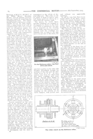
Loosely mounted on the outer ends of the sprocket shaft are a couple of chain sprockets, each of which is provided with a coupring of the type shown in the accompanying diagram ; the sliding portions of these couplings have six jaws, and they ride en feathers on the sprocket. shaft.. This tranverse shaft takes the place of the usual differential shaft ; there is no real differential, but when the steering roller is set for running in a straight line both the chain sprockets are, througfi the medium of the couplings, positively locked to the transverse shaft, but, as soon as the steering roller is moved out of the straight, the near side coupling is disengaged, and the drive is 06 transmitted to the offside of the rear roller only. This roller, it will be noted, is made in halves, each half being positively driven by a chain from the sprocket shaft,
The means by which these sprocket couplings are engaged or disengaged, is shown in the front view which is reproduced ; the cam (C) is mounted on the steering roller spindle, and when in a central position both the couplings are engaged, hut, as soon as the cam moves to one side or the other, the sprocket coupling on the same side becomes disengaged through the medium of the cam and the bellcrank levers D or E. At first, readers may have the impression that these couplings may cause trouble, through their failing to engage at the right time, but our representative made careful observation of the machine under way, manceuvring in and cut of most restricted spaces, and every time the steering roller was moved to right or left, the coupling on the inside of the curve disengaged, and the coupling on the outside of the curve engaged, with perfect ease
and without any appreciable snatching.
It will be seen that there is no engine clutch of any kind ; either of the two speeds, forward or the two speeds reverse being brought into operation quite smoothly, by means of the swinging frictionpulley frame and the selecting coupling for the worm -wheels.
The starting handle for the engine consists of a very long lever, with a pawl that engages with sawshaped teeth on a large quadrant fixed to the dashboard; this lever is mounted on a spindle which is carriea from the head of the cylinders, and on the same spindle is a large chain wheel, which, in turn, is connected by chain to a small free-wheel sprocket on the end of the crankshaft.
A reference to the front view of the roller will show that the frame which carries the steering roller is free to swing on an axis at right angles to the axis of the roller itself, so that the roller may pass over undulating ground without there being anytendency to twist the main frame.
The weight of the roller complete, with tanks full and a TO-stone driver in position, is ,approximately 15 eWt. 1 its cost of operation is remarkably low, and, notwithstanding that, for both forward and reverse travelling, the drive is through a friction belt or pulley, and that the engine is only capable of 'developing li.p., the machine may, with perfect ease, be driven up grass banks and footpaths as steep as I in 8.
In addition to the small motor roller, Mr. Robinson ha.s also designed and built a number of pedaldriven rollers, a photograph of which we reproduce on page 63.
Mr. Robinson is prepared to enter into arrangements with manufacturers for the production of either or both of these machines on commercial lines.