


Automatic Exhaust Braking
Page 82
If you've noticed an error in this article please click here to report it so we can fix it.
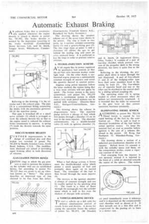
AN exhaust brake that is automatically applied whenever the engine throttle is closed. is shown in patent No. 781,992. The brake. throttle is worked by the depression occurring in the intake manifold. (Cumberland Motor Services, Ltd., and M. Smith, Tangier Street. Whitehaven. Cumberland.)
Referring to the drawing, 1 is the air intake and 2 the exhaust pipe. The pipe (3) is a conventional fitting connecting the intake with the pneumatic governor
(4) -of the injection pump.
This pipe is branched off. to a small. servo cylinder (5) which is arranged to work the exhaust throttle (6), so that as the engine speed is reduced the exhaust brake commences to operate. A spring (7) loads the throttle towards the open position.
DISC-CUM-SHOE BRAKES
FURTHER improvements in the design of combined disc and shoe brakes are revealed in patent No. 781,834 by Bendix Aviation Corp., South Bend, Indiana, U.S.A.. The modifications disclosed are aimed at 'providing equal braking effect in both directions of rotation.
GAS-LOADED PISTON RINGS
pISTON rings in which the gas pressure is used to increase the pressure on the cylinder wall are an established device, but according to patent No. 781,125 they are prone to set up vibration known as " flutter." The patent describes an irnproved type of ring claimed to be free from this defect.
(Goertzewerke Friedrich Goertz A.G., Burscheid bci Koln, Germany.)
The drawing shows . the simplest scheme out of the seven types shown in the patent. The ring is 'made in two parts, an L-section cylinder-contacting -sleeve (I) and a'groove-litting part (2). The ,two rings-mate aL point 3; and a clearance (4) allows the gas to. get behind the sealing ring and exert an extra outward force. It is preferred to key the rings in order to prevent relative rotation.
A PETROL-INJECTION SCHEME
AN oil engine lias its power regulated by qualitative fuel control, so that the air-fuel ratio becomes weaker under light load. On the other hand, a carburctted engine preserves a substantially constant strength of mixture and varies the quantity thereof to control power.
Engines using petrol injection follow the latter method, the reason being that a very weak mixture will not ignite by spark. The former system is the more economical, and patent No. 782,239 shows a combustion system in which even a very weak petrol mixture can be ignited with certainty. (Daimler-Benz A.G., Stuttgart-Unterttirkheim, Germany.) The drawing shows the scheme in diagrammatic form. The injection pump delivers a charge of fuel which first-passes through a 'chamber (l)on its way to the main injector. The chamber' communicates, via a double-headed valve (2) with an ignition chamber (3).
When a fuel charge arrives, it forces open the double-headed valve which passes a small quantity of fuel and promptly shuts again_ on its second head. The remainder of the fuel is then forced through the main injector
The mixture in the ignition chamber is always of constant strength and can be readily ignited by the sparking plug (5). The result is a blast of flame through the passage,46) into the cylinder space which is said to fire even the weakest of charges with certainty.
A VEHICLE-HOLDING DEVICE
TO start a vehicle up a hill calls for delicate simultaneous control of clutch, brake and throttle. A device for easing the operation forms the subject of patent No. 781,973. (W. Dinsdale
and E. Smith, 26 Inglewood Drive, Otley, Yorks.) It coniists of a pair of one-way clutches which prevent rotation of the propeller shaft in the wrong direction, but leave it quite free in the other.
Referring to the drawing, the propeller shaft drive is taken through the unit illustrated. A pair of free-wheels (1 and 2) of the wedging-roller type have their outer members fixed to the casing by keys (3). The free-wheels are of opposite hand and one or the other can be clutched to the central shaft by a sliding splined coupling (4).
The operating slider (5) is spring loaded to allow movement when the 'splines are 'momentarily misplaced. It is intended that the Slider be connected to the gear lever 'so that ,correct operation becomes autOmatic.
ELIMINATING DIESEL ,KNOCK
ACCORDING to, patent NO1 782,136 Diesel knock • is 'caused by too rapid heating of the fuel by the coM bustion air. This is said to lead to chemical breakdown of the fuel before actual ignition occurs. To keep the injected fuel as cool as possible before ignition is the aim of a scheme disclosed in the patent. (H. Krug, .Am Stadtpark 33, Miinchen-Pasing, Germany.)
The drawing shows a section of a spherical pre-combustion chamber at its equator. Helical bores (1) connect it with the cylinder space and these, on the compression stroke, create a vigorous rotation of the air.
Fuel emerging from the injector is not sprayed, instead it is injected in the form of a solid jet directed towards the centre of the sphere. The violent air swirl immediately turns it sideways and it is deposited on the comparatively cool chamber wall as shown at 2. It then spreads out in a thin film and is evaporated by the passing air to burn at a slower rate.