


An Exhaust Brake
Page 64
If you've noticed an error in this article please click here to report it so we can fix it.
131 ATENT No. 737,353 (S. A. Adolphe
Saurer, Arbon, Switzerland), deals with braking a four-stroke engine by means of exhaust throttling. With such a scheme, only one stroke in four is effective, but in the patent is shown a way ins which "two 7 cycle" braking can be obtained.
• The aim is achieved by making the valves operate on every engine revolution when braking is required. In action, the normal exhaust stroke expels its air (fuel being cut off) and the succeeding downstroke induces a fresh charge. On what would be the compression stroke, the exhaust valve is • re-opened to expel the second charge. On the downstroke, the inlet valve re-opens, filling the cylinder for the next stroke.
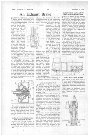
The drawing shows a typical method of" two-cycling " the valves. The • cam (1) lifts the tappet (2) in the normal • way. When the cam has travelled through 180 degrees, it works a rocker (3) which, via ashort push-rod (4), gives the tappet a second thrust. The rocker is eccentrically mounted and can be put in the operative position shown, or by turning the spindle, put put of action as indicated by the chain lines (5). The control lever is mechanically coupled to the exhaust throttle so that they work in unison.
• The patent states that the scheme is alsofeasible if applied to the exhaust valve • only; in this ease its second opening would allow the piston to draw into the cylinder some of the air from the exhaust system and recom, press it.
AUTO-ADVANCE MECHANISM FOR INJECTION PUMPS
PATENT No. 737,238 (Ateliers de Construction Lavallette, 32 Avenue Michelet, Saint-Onen, France) disclosesa centrifugally operated injection pump
B30 advancer. The chief point is that if the transmitted torque be high, the amount of advance is otactly the same as if only a light load were being applied, Referring to the
737i53! drawing, 1 is the spindle of the injection pump, and 2 a pair of dogs for receiving the drive. The dogs drive a sleeve (3) which is Provided with helical splines on its driving end (4) and another set.
(5), of opposite hand, to couple it to the pump spindle.
The sleeve is biased leftwards by a spring (6), and presses on a free running curved disc (7). In doing so, it traps a number of balls (8) against an abutment disc (9) fitted with a ball thrust-race. !
In operation, centrifugal force moves the balls outwards and so pushes the sleeve to the right. In doing so its helical splines advance the pump spindle. By having two sets of splines in series their angle can be kept small, which results in the couplings being irreversible under heavy load. • Any desired charac teristics can be obtained according to the shape of the curve cm the ball plate. massive steel
ALIGHT van having its engine located under the body is disclosed in patent No. 736,208, by G. Palmer, G. Taylor and Yeoman Vehicles, Lid, 4 Playhouse Yard, Blackfriars Lane, London, E.C.4.
The ruiVel feature is that the frame is made from two units disposed at different levels. The front frame (1) is triangular, with its apex at the front, w hilst the rear frame (2) is of X-form.
• with cross-members at front and rear.
• At its-front it is attached to uprights
• (3) which unite it to the lower front frame.
The front spring (4) lies transversely and is clamped to the apex of the front • frame. The retiE springs run longitudinally.
The engine (5). the gearbox (6) and the clutch (7) are in unit construction, but assembled in unusual order. The unit is attached to the lower frame at the front and to the upper one at the rear. The back wheels are driven by universally jointed shafts projecting from the transmission unit. The outer half-axle casings are pivoted to the transmission casing by wishbone links. ELIMINATING BACKLASH IN INJECTION-PUMP CONTROL THERE is always a little backlash I between. the rack-rod and the pinion of an injection-pump control,• and normally it has little effect on the working. But in the case of engines employing pilot injection the backlash can cause serious variation in the pilot charge. A scheme for its elimination is shown in patent No. 737,356 by The English Electric Co., Ltd., 28 Kingsway, London, W.C.2.
The method used is that of springloading the pinion in a rotary sense, and the drawing shows how it is applied. A tappet sleeve (1) is worked by the cam and operates the plunger in the normal way. The sleeve is keyed against rotation by a pin (2) working in a slot in the sleeve.
The bottom of the plunger has a slot (3) across it and this receives the inner end of a volute spring. The other end is anchored in a small hole (4) in the tappet sleeve. The plunger assembly is thus biased towards the non-delivery position, taking up all the rack-andpinion backlash.