


A Four-wheel-steering Design
Page 72
If you've noticed an error in this article please click here to report it so we can fix it.
A &surd of Recently Published , Patent Specifications SPECIFICATION • No. 314,1)64, by Anton Flettner, of Kaiserin Augusta Allee 4, Berlin, calls attention to the fact that as vehicles have gradually been growing larger and heavier, and as larger pneumatic tyres have become more generally adopted, the steering of vehicles requires more effort on the part of the driver to control it, and it is claimed that the present invention will materially reduce the effort required.
The invention appears to resemble the steering arrangements shown in very old prints of the earliest kinds of steam vehicle, where a pilot steering wheel induced movement in the main steering wheels. In the present arrangement, however, the pilot wheels induce movement in a pair of steering wheels mounted in the modern fashion and coupled by means of the track rod, whilst in the early types the main steering wheels turned on a common centre in the middle of the front axle.
The weight of the vehicle is so arranged that only a slight proportion of it rests on the pilot wheels, so making them easy to control. Several examples of the use of the invention are shown, and mention is made of the application of the principle to wheels that are driven as well as steered.
It would appear that no steering movement of the main steering wheels can take place until the vehicle moves either forwards or backwards.
Hydraulic-brake Adjustment. A MEANS for adjusting and equalizing brakes by means of hydraulic pressure is described in specification No. 336,140, by Bendix-Perrot Brakes, Ltd., and H. Clark, both of Westwood Road, Witton, Birmingham.
The brake described is of the kind where shoes are expanded by the cam. The hinges on which the shoes pivot, however, are of the floating type, which permits of a a e 1 f energizing effect being produced by the tendency of one shoe to follow the revolving drum.
In the case of the present invention the hinge is formed by a cylinder and piston, each of which has ft rounded end to enable the shoes to pivot on them. Fluid pumped simultaneously into all the cylinders of the four brakes causes the pistons to extend until the brake shoes meet the drum. The pressure is then slightly relieved and it is claimed that all the four pistons will recede an even distance so as to provide the necessary clearance between shoes and drums, the piston of the pressure-producing cylinder is then locked and the confined fluid is said to form an abutment until fresh adjustment •is needed. A Tipping Body for Low Loaders.
AN ingenious form of tipping arrangement suitable for low-loading, bodies is shown in specification No. 336,013, by J. H. Sparshatt, of 338, Commercial Road, Portsmouth. The specffication points out the difficulty of constructing a tipping body which will discharge its contents by gravity without the rear end coming in contact with the ground before a sufficiently steep angle is attained.
The full lines show the position of the body when in its normal position, whilst the dotted lines indicate its position when tipped. It will be seen that the gearwheel (E) is rigidly connected to the body (B), whilst the gearwheel (C) is rigidly connected to the frame (A). A link connects the two shafts which carry the gears (C and B) which form pivots on which the link can turn. The intermediate gearwheel (D) is free to rotate, and is mounted on a pin • carried by the link.
Simplifying Vacuum Braking.
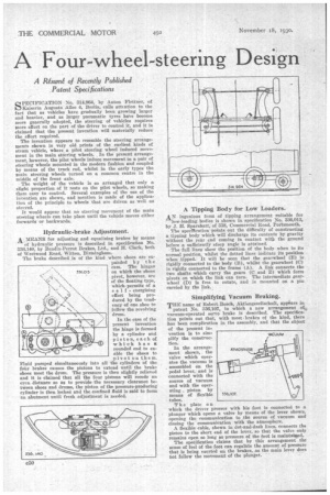
THE name of Robert Bosch, Aktiengesellschaft, appears in patent No. 336,107, in which a new arrangement of vacuum-operated servo brake is described. The specification points out that, with most brakes of the kind, there has been complication in the assembly, and that the object of the present invention is to shnplify the construction.
In the arrangement shown, the valve which operates the vacuum is assembled on the pedal lever, and is connected with the source of vacuum and with the operating piston by means of flexible 356.107 tubes.
The plate on
which the driver presses with his foot is connected to a plunger which opens a valve by means of the lever shown. opening the communication to the source of vacuum and closing the communication with the atmosphere.
A flexible cable, shown in dot-and-dash lines, connects the piston to the short end of the lever, so that the valve only remains open so long as pressure of the foot is maintaitsed. The specification claims that by this arrangement the sense of feel of the foot can regulate the amount of pressure that is being exerted on the brakes, as the main lever does not follow the movement of the plunger. '
amoSPHEQE
vAcuum