


Fitting 1,000 Tyres a Day
Page 45
If you've noticed an error in this article please click here to report it so we can fix it.
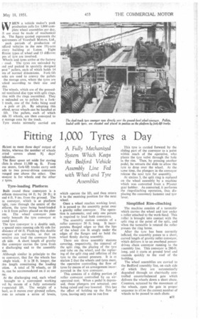
A Fully Mechanized System Which Keeps the Bedford Vehicle Assembly Line Fed with Wheel and Tyre
Assemblies
(v HEN a vehicle maker's peak production calls for 1,000 complete wheel assemblies per day, 11 use must be made of mechanical ds. The figure quoted represents the quireinents of Vauxhall Motors, Ltd.,
peak periods of production of .dford vehicles in the new 191-acre ctory building at Luton. Eight fferent types of wheel and 13 different pes of tyre are involved.
Wheels and tyres arrive at the factory ( road. The tyres are unloaded by Ind and packed in specially designed post" pallets, each of which holds 14 res of normal dimensions. Fork-lift Licks are used to convey the pallets the storage area, where the tyres are 3cked according to their size and ake.
The wheels, which are of the pressed5e1 ventilated disc type with split rings, rive with the rings assembled. They e unloaded on to pallets by a forkI truck, one of the forks being used a pole or jib. By adopting this ethod, seven wheels can be handled at lift. The pallets, each of which Ads 35 wheels, are then conveyed to e storage area by the truck.
Tyre stocks normally carried are
fficient to meet three days' output of :hides, whereas the number of wheels rried covers about 91 days' .oduetion.
The floor space set aside for storing illets is about 11,500 sq. ft. From cse stores, fork-lift trucks carry unit ads to two power-driven conveyors ranged one above the other. One inveyor is for wheels and the other r tyres.
Tyre-loading Platform
Built round these conveyors is a atform measuring 64 ft. by 20 ft.; it and 4 ft. 9 ins, from the ground. The re conveyor, which is at platform :ight, runs through the centre of the atform, the tyres • being hand-loaded to it from pallets placed on the platrm. The wheel conveyor runs rectly beneath the tyre conveyor at ound level.
The tyre conveyor is a double unit, e spaced units running side try side for distance of 64 ft. Flanking this double onveyor are cat-walks, so that an )erative can load the conveyor from .ch side. A short length of gravity iller conveyor carries the tyres from e discharging end to the assembly )int.
Although similar in principle -to the re conveyor, that for the wheels has single track. It is 28 ft. longer, the itra length constituting the loading ction. A total of 70 wheels, or 10 ts, can be accommodated on it at one me.
At the discharging end, each wheel brought to a convenient working vel by means of a fully automatic r-operated lift. The weight of a heel, as it moves over pivoted rollers, rves to actuate a series of levers,
which operate the lift, and then return it to the receiving position for the next wheel.
Once a wheel reaches working level, it is passed to the assembly point over a gravity roller conveyor. The operation is automatic, and only one person is required to load both conveyors.
The assembly station consists of a roller conveyor 50 ft. long. It incorporates flanged edges so that the lips of the wheel rim fit snugly under the edges of the flanges and so hold the wheel firmly during assembly.
There are three assembly stations covering, respectively, the removal of the split ring, the placing of the tyre and tube on the wheel, and the replacing of the split ring and inflation of the tyre to the correct pressure. It is at station 2 that the wheels and tyres meet, the operative controlling the flow of tyres by means of an arrangement incorporated in the tyre conveyor. This consists of a sliding portion of roller conveyor controlled by an air-; operated ram. When a pedal is depressed, three plungers are actuated, one being raised and two lowered. This has the effect of holding up the flow of tyres, leaving only one to run free This tyre is carried forward by the sliding part of the conveyor to a point within reach of the operative, who places the tyre valve through the hole in the rim. Then, by pressing another pedal, he retracts the slide to allow the tyre to drop over the wheel. At the same time, the plungers in the conveyor release the next tyre for assembly.
At station 3, the split ring is replaced on the wheel assembly by a machine which was converted from a Pfauter izear bobber. As converted, it performs the ring-clinching operation, thus displacing the customary hammer and tyre lever,
Simplified Rim-clinching
The machine consists of a turntable which carries the wheel and tyre under a roller attached to the work-head. This roller is brought into contact with the split ring at the point of the split, and when the turntable is rotated the roller presses the ring home.
After the tyre has been correctly inflated, the assembly passes to a short, curved length of gravity roller conveyor, which delivers it to an overhead powerdriven chain conveyor running to the assembly line. This conveyor is 280-ft. long, and it starts at ground level and ascends quickly to the roof of the building.
The wheel assemblies are carried to the Bedford assembly line, on each side of which they are automatically deposited through an electrically controlled counterbalanced gate which delivers the wheels down a short chute. Counters, actuated by the movement of the wheels, open the gate in proper sequence to ail aw the-correct number of wheels to be passed to each chute.