


FORD VAN POINTERS.
Page 22
Page 23
Page 24
If you've noticed an error in this article please click here to report it so we can fix it.
By R. T. Nicholson (Author of "The Book of the Ford ").
RESUMING. my analysis of the ilectrical circuits of the 1920 Ford, I will now deal with the three circuits which have the magneto as their source of energy and then with the circuits passing through the coil windings.
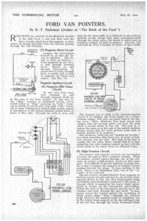
(7) Magneto-Horn Circuit.
Imagine the horn-button ;pressed in, so that the circuit is complete. The circuit is then as -follows :— From magneto by RED wire, to and through terminal block ; thence to and through horn-switch, by BLACK wire to horn, through horn, to earth, and so back to magneto by frame and engine. See Fig. 138.
Magneto-Ignition Circuit.
(8) Magneto-Mil-Timer Circuit.
By up) wire from magneto terminal to and through terminal block (as in the ease of the horn circuit); by RE)) wire to the "Mag." terminal in dashboard switch, across switch (when in " Mag." position), to " Coil" terminal in switch, by BLACK wire from said " Coil " terminal to Same binding-post behind dash as,..was named in description of the battery-ignition circuit (para. 6) (issue of May 4th). Through the coils in turn, and
HORN
FIG 138 BUTTON then by the same path as is followed in the battery. ignition circuit, except that, after passinetotearth through the timer roller, the circuit is taken back to megnetor instead of back to battery. See%Fig. 139, and‘looklup First Principle II (issue of April 20th).
The. clearest way to think of the magneto-ignition circuit is to imagine the Ford engine as a. singlecylinder engine, with only one metal inset in the timing cover. Then, whenever that inset comes into contact with the moving roller, you have the path which is clearly shown in Fig. 140. The path is, of course, the same as in the case of the battery-ignition circuit, except that the earth portion lelds back to battery instead-of to magneto.
But, of course, when you are "looking for trouble," you must remember that there are in point of fact, four circuits, not one only. But each of the four is exactly like the other three, except that it is completed (by the roller making contact in turn with the metal insets in the timer cover) at different times.
(9) High-Tension Circuit.
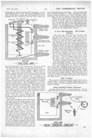
The battery and magneto currents 4re low-tension currents throughout their complete circuits. When low-tension current passes through one of the coilunits, it excites a high-tension current in that same unit. It is difficult to get the beginner to grasp this. He is apt to im,agine the magneto or battery current passing through the plugs. It does nothing of the kind. Here is an illustration (Fig. 141) of the "innards" of the coil-unit.
The low-tension current (whether from magneto or battery) passes into the ooil-unit by the 'bottom binding-post shown in Fig. 141, that binding-post being eleetrine.11y (and internally) connected te the plate C, through which it passes:up the heavy black spiral,
which . known as the low-tension
Follow the path of the low-tension current up to the vibrator arm post, through the am itself. It then passes across the contact points—the trembling of which makes them " buzz "—through the, vibrator itself whenever the contacts touch by trembling, out by The folded brass support at the top left-hand side of the ,eoil box. through the heavy horizontal black
connection to the top spring clip connection, to the top binding-past (to each of the top binding-posts in turn, as the timer makes the four contacts in turn), through the four coloured wires (in turn) which run from these posts to the timer cover, and so to earth through the tinier roller, as has been described:
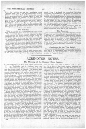
In Fig. 141 the vibrator contact is shown as being tight against the vibrator bridge contact—that is, closed. This is its normal position. When, however, current passes through the low-tension i coil, through these contacts, it has to pass round the.bundle of iron wires--or core—shown in.,Fig 141. In doing so it magnetizes the wires. (This is a well-known electrical fact.) The core, therefore, pulls down the spring contact, so that the paints open, andthe low-tension circuit 18-. interrupted. But immediately it is interrupted, current ceases to flow in the low-tension coil, and the core loses-ins magnetism. The lower contact spring, therefore, jumps up again, and again makes contact, thereby completing the citeuit once more. So we get. a series a makes and breaks,-of current, and every time the circuit is made or broken we get a rush of high-tension current in the second (fine) coil and a spark at the plug. It is this constant making and breaking of the contacts that causes the coil to buzz, Butthe interesting point about the coil-unit lies in the high-tension winding, represented in the illustration by a long spiral of thin wire:The very fact that the low-tension current passes through the thick, •short-wire spiral starts a high-tension current in the long, thin-wire spiral—a 'current of enormously higher voltage (ori greater vim) than the low-tension -current. Do not ask me why this happens ; it does: and the happening is known as " induction." The high-tension current passes • out from the. fine wire spiral through the lower spring connection (B), to. one of the four lower binding-posts which carry the sparking-plug cables. So the high-tension current passes in -turn to the individual plugs, juinps the gaps and earths through plugs and engine. (As to jumping the gap, see First Principle I.) After earthing, the higln tension current completes its circuit throirgli engine and fraine, by the low-tension Wires (from timer to upper row of binding-posts behind dash),4back to coil and upper spring connection clip (A), which, it will be seen, is in contaettwith both the low-tension spiral and the high-tension spiral in the coil-unit. So the high-tension gets " hospe " to the high-tension spiral, whence it started. (See First Principles I. and IL) Fig. 10 shows the high-tension circuit.
A Few Odd Remarks: The Colour Scheme.
The wires are coloured, with the idea, that you may be able to trace them. But do not imagine that, because a particular -colour is chosen for some particular wire, -that colour cannot be use4 for same totally different circuit elsewhere because it can. For instance, there is one black wire fronithorn-switch to terminal block, KO that you would naturally expect to find a black wire from hoirn-switeh to horn—as you do ; but you might not expect to find a black wire from a, coil-unit (No. 1) to , the timer, or from dashboard switch battery terminal to ammeter, or from ammeter to cut out, or from dashboard switch "coil" terminal to coil binding-post; but all these wires are black. There are manyother cases where the same colour is used in different circuits.
. The fact is that there areamt enough colours available to make it possible to keep one for each individual circuit,. The colour is only meant to guide you when there is a danger of yournot being able to trace a particular wire—e.g.' when it passes under a cover or "loom "
(as it is ealled), or. through,somelind of "tunnel," so
that you lose sight ofth forthe time -being. When
you car' plainly see the whole length of a wire, there is neP need of a.. colour scheme. But when you see a wire of a. certain colour go under cover, you can only recognize it when it -comes out again-by its being of the same:colour.
The "Looms."
The purpose of binding together single wires into a. cluster under aloom is tokeep them tidy, and to ,prevent their insulation getting chafed through rubbing or cutting.
Wires Serving Various Purposes.
A single wire-Jnay serVe v,ariousgairposes. For instance, the heavy yellow *ire that carries the current from the battery serves the headlights (both "Bright" and "Dim "), the tail light and the battery ignition; more than that, it also tarries the current in the generator-battery circuit (Para. 2) from the
ammeter towards the battery. So, too, the low-tension wires that carry the current from coils to timer also ocnvey the high-tension current from "earth" after it leaves plugs and frame, to the high-tension coil spirals. And so on: Do not be perplexed by this. Electricity can always be trusted to sort itself out ; it does not get tangled up in itself. Read First Principles land II again—and again.
The 'Switches.
Think of a, switch as a swing bridge, by which, when shutaa, current can pass what was previously a gap.
The foot-switch has no conceru whatever in any circuit except the power-starter circuit (Para. 1). Unless you get that clearly in your mind, you will get hopelessly fogged in tracing the other circuits that run under. (and, seemingly through) the foot-switch.. The dashboard switch is most cleverly constructed.
For instance, it is So made that if the lighting circuit is closed by turn of the switch lever to either "Bright" or " Dim" position, the tail lamp must. also light up. This. is necessary, because your tail lamp should always be alight, 'whether either " bright " or
" dim " headlights are required. .
The dashboard switch is also so made that the battery-ignition circuit (Para. 6) Inuit be open (by means of the short Yale key) when the magneto-ignition
circuit (Para. S.) is closed, and vice versa. It is thus impossible for the battery to connect up through the switch, with the magneto. If there were such connection, grave damage would be done to the magneto.
The dashboard switch has no concern whatever with the generator-battery circuit (Para. 2), which is always closed 'by the out-out (itself an automatic switch) when the engine is running fast enough.The cut-out opens again, arid. so breaks the circuit, when the engine slows down, or stops.
Nor is the dashboard switch concerned bo with the battery-power-starter circuit (Para. 1). The only switch concerned with that is the foot-switch.
The Ammeter.
The ammeter registers only in the lighting circuits (Para& 3, 4, and 5), and in the generator-battery circuit (Para. 2). Theoretically, it should also register in the battery-ignition circuit (Para. 6), but in practice, the drain is so slight in that circuit, that the amineter takes no account of it in "Discharge." . The ammeter is not in the magneto-ignition circuit (Para. 8), noi`in the power-starter circuit (Para. 1). It. therefore does not register " Discharge" in either of these cases.
Conclusion (for the Time Being).
I have now finished dealing with a complicated subject, and it is complicated when you first begin to think about it ; but. I hope that I have kept my promise to "make it clear."