


Swash-plate-operated Injection Pump
Page 34
If you've noticed an error in this article please click here to report it so we can fix it.
A Résumé of Patent SpdJications That Have Recently Been Published
A N injection pump, operating on the swash-plate principle, is shown 'n
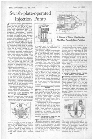
patent No. 552,547, by R. L. 'Kent, Penn Cottage, Coleshill Road, Marston Green, near Birmingham, and J. N. JI.lorria, 38, Richmond Hill Road, Edgbaston; Birmingham. Intended for four-stroke engines, the pump is provided with half as many plungers as there are engine cylinders, a distributor being employed to direct the fuel to the appropriate injector.
A stationary plunger block (1) houses the plungers which are springloaded in an outward direction. Working movement comes from a wobbler (2), which is hemispherical in form and works on a curved seating in the casing. For output adjustment, the wobbler is given a variable throw, the control mechanism comprising a slider which moves an oblique sleeve (3) in an endwise direction. The rotary motion of this sleeve generates a conical outline which is transmitted to the wobbler via a special . bearing (4). By sliding the sleeve (3), the amplitude of the wobbler can be varied between its maximum and zero, the left-hand end of the sleeve being approximately concentrio.
The -distributor comprises a disc valve, made in two parts (6 and 7), which are pressed apart, by springs to form a seal on both faces. The disc valve is actuated by an eccentric (9) on the spindle, whilst it. is also geared to the case, so that, in addition to • the eccentric motion, it also progresses epicyclically. The valve connects each of the plunger ports (5) with alternate openings (8) in the back plate which lead to the individual injectors. The valve chamber (10) also acts as a fuel-supply space, the eccentric • motion uncovering inlet ports as the plungers move on their outstroke.
IMPROVED MAIN BEARING FOR V-TYPE ENGINES AUCH research now being carried 1VIout in the design of aircraft engines will, ultimately, become available in the world of road transport, and an example of this isgiven in patent No. 552,247, by the Ford Motor Co., Ltd., 88, Regent Street, London, W.1. The patent discloses an improved design of main bearing for V-type engines, the object being to attain great strength with a, decrease
in weight, and to avoid excessive width, a feature of importance in multi-cylindered engines. • Our drawing shows a crankcase web' (2), a bearing cap (4), and, in section, one of the crankshaft main bearings. The chief novelty lies in the layout of the bolts; two sets are employed, spaced angularly as shown, whilst they are also staggered slightly in the other direction to permit of a cross-over.,
Actually, they are studs, being fitted with ordinary nuts at the lower end, and screwed into cylindrical nuts (1, 3 and 5) housed in bosses on the crankcase web. The nut 1 has two holes to accommodate its pair of studs.
The angle between the two sets of bolts is equal to that between the cylinder banks, so that theiorces from each cylinder are encountered by straight tension in one pair of studs, and no bending stresses are applied to the cap. All surrounding excess metal can be cut away, the four studs and the cap forming a self-contained structure.
PISTON RINGS FROM POWDERED METAL DET-AILS of the processes involved in forming piston rings from powdered metal are given in patent No. 552,532, by the British Piston Ring Co., Ltd., Holbrook Lane, Coventiy, and others. Such rings, after being solidified by heat, tend to show distortions, and the patent deals with a method of correcting this.
After sintering, as the heating operation is called, the ring is placed in a die, which tapers down to the desired shape, and then pressed home by a punch. This operation is performed cold, or, at least, at a temperature insufficient to oxidize the metal. Finally, the ring iiAsubjected to an annealing operation.
AUTO-CENTRIFUGAL CLUTCH OF COMPACT DESIGN
THE addition of means for centrifugally operating a clutch usually demands extra space to house the bobweights or their equivalent ; to minimize, if not to avoid this, is the object of an improved dpsign shOwn in patent No. 551,378, by N. 13. Newton, Newton and Bennett Works, Acton, London, W.3.
Our drawing shows sufficient of a clutch to illustrate the scheme, A pair Of driven plates (3) is employed, between which is sandwiched a thick driving plate (1). The latter is made in two parts, kept together by springs and opened by the wedging action of a number of steel balls housed in a pail of sloping recesses. It is easy to appreciate how the central plate is expanded into ,contact as the balls move outwardly with an increase in engine speed.
To permit of manual disengagement, the expansion of the central plate is limited by bolts (4), sb that the working pressure can be relieved by retracting the presser plate (2).
A QUICKLY DISMANTLED FILTER FOR SMALL FIRE PUMPS
iINTENDED principally for the cooling systems of.,small motor fire-pumps, a quickly cleaned filter is shown in patent No. 552,467, by Coventry Climax Engines, Ltd., L. P. Lee and L. Hathaway, all of Friars Road, Coventry. The chief object is to enable the filter to be cleaned without stopping the engine, which means that the cooling system can be interrupted for only a limited time bfefore the water starts to boil.
Referring to -the drawing, the inlet (5) and the outlet (2) are both located in a fixed, upper portion of the body.
The water is directed through a wiremesh filter (4) by suitably formed passages. The lower bowl can be quickly detached by releasing a centrally disposed bolt' (1) whilst correct reloca. tin, on assembly, is ensured by the use of a dowel (3), a point of considerable help in the dark,