


Patents Completed.
Page 22
If you've noticed an error in this article please click here to report it so we can fix it.
A New Wolseley Chain and Spur Gearbox.
The Wolselev Tool and Motorcar Co , Ltd., and A. -J. Rowledge, No. 17,651, dated 3rd August, 1911, Cognate Appl
cation No. 21,199;1911.—This specification describes a gearbox in which the bulkiness of chain-driven gearing is largely avoided by the use of combined chain and spur-gearing, without sacri ficing any of the advantages. In tha construction illustrated, the driving and driven shafts are arranged in line with one another in the usual way, and a clutch is arranged to couple them together for a direct drive on the top speed. A chain drive is taken from the driving-shaft to the lower end of the countershaft so that the latter is con stantly driven. For the second speed the chain drive at the upper end of the countershaft on to the driven shaft is used by clutching the pinion to the connter;haft. The third speed is obtained by spur-gearing. A sleeve on the countershaft, carries three gear wheels, one of which can be brought into mesh with a gear on the driving-shaft, and the other two (which are the same size) with a gear on the driven shaft. In the position illustrated, the third or lowest speed is obtained by moving the sleeve upward in the direction of the arrow, so that the countershaft gear wheels are meshed with the driving and driven-shaft gear wheels, and the drive is transmitted entirely through spur-gearing. The reverse is obtained by moving the countershaft sleeve downwards and clutching it to the first chain wheel on the countershaft. The third spar-wheel on the sleeve then engages the spur-wheel on the driven shaft, so that the drive is transmitted first by chain and then by spur-gearing. The control may be effected by a single lever need in conjunction with a gate in the usual way. A modified construction of this gearbox is also described.
A Novel Two-stroke Motor.
G. L. M. DerwaId, No. 13,769, dated '9th June, 1911.—In this engine only pure air is compressed into the combustion chamber in the ordinary way, and the fuel is injected at a higher pressure at the required time. A scavenging-air inlet port, and an exhaust port, are arranged to be opened by the piston when near the bottom of its stroke. Inside the piston and above the gudgeon. pin, there is fixed a horizontal cylinder containing a plunger which is reciprocated by a tongue on the back end of the connecting rod. This plunger forms a double-acting air pump and compresses. at one end or the other, air which is fed into the combustion chamber through a valve on the main piston operated by the pump-plunger engaging a trip-lever. Below the gudgeon-pin two fuel pumps are fixed on the piston, and a common plunger is operated by a pin on the connecting-rod. The inlet to these pumps is formed by a tube on their underside which, when the engine piston is at the bottom of its stroke, telescopes over a tube standing up from a braCket on the side of the crank chamber, and supplied with fuel from a float chamber in the ordinary way. When this telescopic joint has been made, the pump takes in its supply of fuel and feeds it in due course to a jet where it is atomized by compressed air from the air pump above described. Only one of the fuel pumps is in use at one time, and the engine is reversed by stopping the supply to that pump and opening the other.
More Swivelling Head-lights.
H. R. Hepworth and W. Wood.—No. 17,632. dated 3rd August, 1911.—The head-lights on a motor van are moved to throw the light directly into the course of the vehicle. This is done by coupling the rotatable spindles on which the lights are carried by a chain to a chain-wheel, fixed above the swivel-pin of the front-axle of the van. Instead of a chain-connection, a belt and pulleys may be used, in which case it is advis• able to pin the belt to the pulley to prevent slipping.
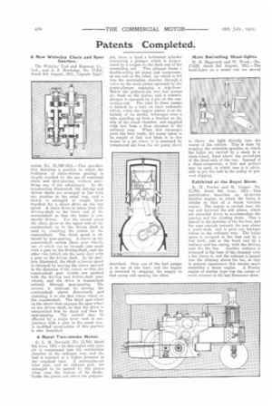
Exhibited at the Royal Show.
R. H. Fowler and H. Cooper, No. 13,704, dated 8th June, 1911.—This specification describes an oil-driven traction engine, in which the frame is similar to that of a steam traction engine. The engine is carried near the top and between the side plates, which are extended down to accommodate the gearing and the winding drum. This is placed in the position of the fire-box, and the rope extends towards the rear above a water-tank, and is paid out between rollers in the ordinary way. The boiler space is occupied at the rear end by a fuel tank, and at the front end by a radiator and fan casing, with the driving gear for the fan. Another radiator is arranged in the base of the chimney with a fan above it, and the exhaust is passed into the chimney above the fan, so that in general appearance this tractor much resembles a steam engine. A Fowler engine of similar type was the centre of much interest at the last Doncaster show.