


Latest Contribution to Pilot Injection
Page 11
Page 12
If you've noticed an error in this article please click here to report it so we can fix it.
The Future of the Oil Engine Depends Largely Upon the Progress Made in Fuel Injectors and Pumps
THE oil engine, as used on cornmereial vehicles, is rapidly replacing petrol units, especially in the heavier field, and is even encroaching in the case of lighter transport media. This type of power unit has, however, certain disadvantages; scantlings must he sufficiently strong and heavy to withstand the extra stressing and vibration caused in particular by what is known as "Diesel knock," and partly for this reason it is considerably more expensive than the petrol type.
In the oil engine, combustion is normally extremely rapid and more in the nature of an explosion, and this is the main reason for the knock, which may, in a unit of fair size, result in "hammer blows" of 8 tons or so on each piston. With a six-cylindered engine running at only 1,200 r.p.m., each piston receives 36,000 such blows per hour, whilst the crankshaft is subjected to 216,000.
Reduced Stress
To modify such blows and, as it were, spread the explosion, recourse is being had to pilot, or two-phase, injection, some of the fuel being injected earlier than the main quantity. Various ways have been devised for effecting this, and a practical solution of the problem should permit oil engines to be built lighter, possibly little heavier than petrol units of corresponding power.
It must be emphasized that it is not the purpose of pilot injection to reduce the overall height of the indicator diagram, as it is the top of this which makes possible the economy of the oil engine, but rather to "iron out" the bad kink between the end of cornpres
sion and the combustion peak pressure, replacing this as nearly as possible by a smooth line.
One of the most interesting and, incidentally, simple of these pilot injectors is that invented by Mr. G. S. Kammer, of Trumpet Hill, Reigate, Surrey. He recognized that to obtain good performance from the initial charge, high atomization is necessary. Now, the amount of discharge from a given orifice depends approximately upon the pressure of the liquid. Halve this, and about half the amount of fuel issues in a given time. Unfortunately, if the pressure drops the spray velocity is reduced and the atomizing diminished, and the larger the droplets the longer will be the delay period between their. injection into the highly compressed air and the first appearance of a flame.
It is desirable, therefore, to maintain a high pressure of fuel discharge from the beginning of injection. This requires not only control of the pressure, but also of the area. Theoretically, the poppet valve can achieve this, but in practice the lift is so small that metering accuracy and balanced inter-cylinder distribution by its control are extremely difficult.
Two-phase Injection
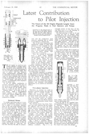
Therefore, an attempt was made to develop a selective nozzle, one that will operate with a variable number of orifices—few during the pilot period and more during main injection. This has been tried previously by others, using twin-needle valves •per injector, whilst for some time the Bosch concern marketed a stepped-pintle nozzle based on this principle. The limiting factor has been, however, that pilot injection did not extend for sufficient time to cover the delay period, because storage for the excess fuel was small, consisting mainly of Oa volume freed by the lifting needle. To overcome this, positive means for "storage" were sought, and it was considered essential that this should help to govern the pilot-diseharge pressure and provide accurate timing of the pilot fuel over the speed range. Fig. I shows a complete injector resulting from this policy and actuated by standard fuel-injection pumps with ordinary camshafts. Fig. 2 is an enlarged section of the base of this, and both carry at A the lettering to which reference is how made.
The fuel entering is lead via B and a cavity (C) into an annular space (D) formed by the control plunger (E) and its barrel (F). Space D communicates with the pilot check valve (H), which is spring-loaded and opened by fuel under pressure. The flow is then through channel 1 into lead J in the selector screw (K), continues through the selector pin (L) and discharges through pilot orifices in the nozzle teat (M).
The control plunger (E) is loaded by a spring of such value as to yield under the fuel pressure from the pump, but the fuel cannot all be ,discharged through the limited jet area provided for pilot injection. The plunger therefore recedes simultaneously. Thus the pressure cannol exceed the value determined by t be control spring, nor can it fall below it, because in that case the plunger immediately drops. In rising, plunger E eventually uncovers a port (N5 and fuel proceeds via lead 0, opens the main valve (P) and passes via lead Q and flutes R to the pocket (S) in the bulge of the nozzle above the teat, where are the main orifices, which then join the pilot ones in discharging fuel.
Until the end of the required injection period both sets of orifices continue to function. Whilst the injection 'pressure during the pilot period was controlled by the control spring, the pressure of main injection is governed only by the contour of the fuel-pump cam, as in conventional injectors, because plunger E is arrested by the lower face of the nozzle holder (T).
When spill occurs in the fuel pump and pressure drops under the control plunger, the two valves (P and H) snap shut and the plunger drops. A special delivery valve at the pump end gives line pressure control and permits fuel to flow back from under the plunger. In conventional injectors the valveclosing pressure is lower than the release presSure to which the injector is set. I his is not so in the Kammer device The valves H and P are not only closed by their springs, but forced on to their seats by the gas pressure in the engine cylinder acting through the fuel via the nozzle.
Quick Cut-off for Valves
During pilot injection the pressure is comparatively low, say, about 450 .1b. per sq in. but when injection ceases the pressure has risen to probably about 1,000 lb. per sq in. Thus there is .a sharp 'clean, fuel cut-off which prevents secondary preSsure waves from reopen:ing the valves. This keeps the nozzle free from carbon, whilst the unusually large volume of fuel in the nOzzle helps to keep the temperature tow. "Fhe valves being in a cool zone, the seats should last longer.
The good sealing resulting from this factor should also assist in keeping the injector nozzles clean and free. The two valves of each injector, which are identical in size and shape, should be comparatively easy to machine and can easily he replaced, Fig. 3 shows a combined pump and injector also operated by a " singlerate " fuel ram. The valve arrangement is similar to that explained, but storage means for excess fuel is provided by a control orifice (U), which spills into the inlet trunk, or gallery, until covered by the rising pump plunger. As.this orifice is closed a nom (V) is opened by the lower edge of the pump helix, so that fuel can then reach the main nozzle orifices. By calibrating the control orifice (U) any desired pilotfuel pressure is obtainable.
Injection Control Simplified
Any type of injection is also possible by manipulating the number and size of both pilot and control orifices, whilst the size and number of the main orifices, together with the pump-cam contour, provide full control over the main discharge Any desired timing can also be afforded by moving control orifice U and port V up or down relative to the plunger. The limits of timing and metering can be kept remarkably close over a wide range'of engine speeds.
The unit pump and injector shown in Fig. 3 is being used for an engine of 4-in, bore, which, it is believed, will soon appear on the market.
We are informed that several British makers are expressing considerable practical interest in the Kammer pilot injector, and that power units embodying it are already working abroad. Extensive tests have been conducted in this country, and although full details are not yet available it is said that no cokingof the nozzle has occurred after 200 hours of running.
This method of injection is the result of experiments covering a period of nearly four years, and we are sure that many operators of oil engines will look forward with great interest to further news of this cleverly conceived but simple system.