


Overhauling Link Motion.
Page 20
Page 21
If you've noticed an error in this article please click here to report it so we can fix it.
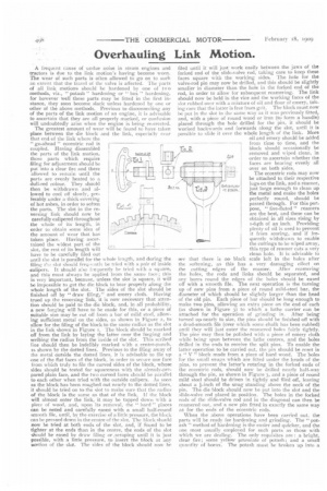
A frequent cause of undue noise in steam engines and tractors is due to the link motion's having become worn. The wear of such parts is often allowed to go on to such an extent that the travel of the valve is affected. The parts of all link motions should be hardened by one of Le o methods, viz., " potash " hardening or " box " hardening, for however well these parts may be fitted in the first instance, they soon become slack unless hardened by one or other of the above methods. Previous to disconnecting any of the parts of the link motion of an engine, it is advisable to ascertain that they are all properly marked, or confusion will undoubtedly arise when the engine is being re-erected. The greatest amount of wear will be found to have taken place between the die block and the link, especially near that end of the link where the "go-ahead " eccentric rod is coupled. Having dissembled the parts of the link motion, those parts which require filing for adjustment should be put into a clear fire and there allowed to remain until the parts are evenly heated to a dull-red colour. They should then be withdrawn and allowed to cool off slowly, preferably under a thick covering of hot ashes, in order to soften the parts. The slot in the reversing link should now be carefully calipered throughout the whole of its length, in order to obtain some idea of the amount of wear that has taken place. Having ascertained the widest part of the slot, the rest of its length will have to be carefully filed out until the slot is parallel for the whole length, and during the filing the slot should freuu.: nthbe tried with a pair of inside calipers. It should also frequently be tried with a square, and this must always be applied from the same face; this is very important, because, unless the slot is square, it will be impossible to get the die block to bear properly along the whole length of the slot. The sides of the slot should be finished off by "draw filing," and emery cloth. Having trued up the reversing link, it is now necessary that attention should be paid to the die block, and, in all probability, a new forging will have to be made for this, or a piece of suitable size may be cut off from a bar of mild steel, allowing sufficient metal on the sides, as shown in Figure 2, to allow for the filing of the block to the same radius as the slot in the link shown in Figure I. The block should be marked off from the link by laying the latter over the forging and scribing the radius from the inside of the slot. This scribed line should then be indelibly marked with a centre-punch, as shown by the dotted lines. Previous to the filing away of the metal outside the dotted lines, it is advisable to file up one of the flat faces of the block, in order to secure one face from which truly to file the curved sides of the block, whose sides should be tested for squareness with the already-prepared plain face, and the two curved faces should be parallel to each other when tried with the outside calipers. As soon as the block has been roughed out nearly to the dotted lines, it should be tried on to the slot to make sure that the radius of the block is the same as that of the link. If the block will almost enter the link, it may be tapped down with a piece of wood, and, upon its removal, the " hard " places can be noted and carefully eased with a small half-round smooth file, until, by the exercise of a little pressure, the block can be pressed down in the centre of the slot. The block should now be tried at both ends of the slot, and, if found to be tighter at the ends than in the centre, the ends of the slot should be eased by draw filing or .scraping until it is just possible, with a little pressure, to insert the block at any uortion of the slot. The sides of the block should now be filed until it will just work easily between the jaws of the forked end of the slide-valve rod, taking care to keep these faces square with the working sides. The hole for the valve-rod pin may now be drilled, and this should be slightly smaller in diameter than the hole in the forked end of the rod, in order to allow for subsequent reentering. The link should now be held in the vice and the working faces of the slot robbed over with a mixture of oil and flour of emery, taking rare that the latter is free from grit. The block must now be put in the slot in the same way as it was previously fitted, and, with a piece of round wood or iron (to form a handle) placed through the hole drilled for the pin, it should be worked backwards and forwards along the slot, until it is possible to slide it over the whole length of the link. More oil and emery should be added from time to time, and the T3 5_1. block should occasionally be removed and wiped clean, in order to ascertain whether the faces are bearing evenly all over on both sides.
The eccentric rods may now be attached to their respective lugs on the link, and a reamer, just large enough to clean up the metal and make the holes perfectly round, should be passed through. For this purpose, " five-fluted " reamers are the best, and these can be obtained in all sizes rising by 1-64th of an inch. Providing plenty of oil is used to prevent it from scoring, and if frequently withdrawn to enable the cuttings to be wiped away, this type of reamer cuts a very clean hole. It is advisable to see that there is no black scale left in the holes after the softening, as this has a very damaging effect on the cutting edges of the reamer. After renmering the holes, the rods and links should be separated, and any burrs round the edges of the holes should be eased off with a smooth file. The next operation is the turning up of new pins from a piece of round mild-steel bar, the diameter of which should be slightly larger than the head of the old pin. Each piece of bar should be long enough to make two pins, allowing an extra piece on the end of each (as shown in Figure 3) to which a lathe carrier can be attached for the operation of grinding in. After being turned up nearly to size, the pins should be finished off with a dead-smooth file (over which some chalk has been rubbed) until they will just enter the reamered holes fairly tightly. The pins may then be polished with a piece of emery cloth while being spun between the lathe centres, and the holes drilled in the ends to receive the split pins. To enable the latter operation to be carried out, the pin should be reset in a " V" block made from a piece of hard wood. The holes for the small snugs which are fitted under the heads of the pins, to prevent the latter's rotating in the forked ends of the eccentric rods, should now be drilled nearly half-way through the pin, as shown in Figure 3, and a piece of round mild steel should be driven in tightly and filed off, leaving about a einch of the snug standing above the neck of the pin. The die block should now be put into the slot and the slide-valve rod placed in position. The holes in the forked ends of the slide-valve rod and in the diagonal can then be reamered out, and a new pin fitted in exactly the same way as for the ends of the eccentric rods.
When the above operations have been carried out, the parts will be ready for hardening and grinding. The "potash " method of hardening is the easier and quicker, and the one most usually employed for such parts as those with which we are dealing. The only requisites are : a bright, clear fire; some yellow prussiate of potash ; and a small quantity of borax. The potash must be broken up into a
powder, and mixed with about one-quarter its bulk of powdered borax. There are several compounds on the market which possess good hardening qualities, but, if properly handled, the above ingredients will answer the purpose quite as well, and can be obtained almost anywhere. The link may now be placed in the tire, and, when it has attained a bright red heat, it should be removed, and, with a spoon, the potash powder may be sprinkled over the faces in the slot and in the eccentric rod holes. The powder will fuse and run in the form of a liquid. Fresh potash must be added until the link has cooled down to a dull-red heat. The operations of heating and sprinkling are then repeated until the link again reaches the dull-red heat, It must then be quenched in cold water. The hard skin which is created by this process of hardening will be about 1-32nd of an inch in depth. The working faces are, therefore, quite hard, although the metal underneath that skin is comparatively soft. The die block and pins can then be treated in precisely the same manner, but it is not necessary to harden the heads of the pins. In order to avoid the possibility of warping the pins, they should be plunged into the water vertically. The faces being now quite hard cannot be attacked with a file, and any adjustments which are required will have to be effected by means of grinding. The die block will be found to be too tight in the slot in the link, and it will have to be reground with oil and flour of emery, as previously described, and the pins must be ground into their respective holes with the same abrasive medium. The extra length which was left on the pins for the purpose of gripping them while being ground into the holes can now be sawn off, and the heads filed flush and polished. The parts already mentioned are the ones that will be found to have worn more than any of the others, although the pins in the drag links or rods connecting the forked pieces on the " weigh-shaft " with the upper part of the reversing link should also be examined, and, if necessary, renewed. This also refers to the pins in the side rod and reversing lever. The keys in the forked pieces on the " weigh-shaft" should now be tested for any slackness, and, if necessary, new keys must be fitted. Take up any slack in the shaft bearings, so that, when the caps are bolted " hard up," they are just a free working fit. The tongue piece on the reversing lever is often found to have worn the quadrant where it engages in the "go-ahead " notch, and this notch will probably have worn until it is larger than all the others. If so, it will be necessary to file the others to the same size, and to fit a new tongue piece on the reversing lever. This is best done by cutting off about 3 inches from the end of the old tongue piece, and welding on a new end, which must then be filed to fit the correct notches in the quadrant. The parts should then again be hardened. The notches should be filed slightly tapered, as shown in Figure 4, in order to facilitate the engagement of the tongue piece. If the taper is excessive, and the tongue spring is weak, the lever is liable to move along the quadrant when not required to do so. There should be a full t-ifith of an inch clearance between the bottom end of the tongue piece and the bottom of the notches. This is in order to allow of the tongue's bearing on the side of the notch.
The whole of the link motion should now be thoroughly cleaned, in order to remove all traces of the flour of emery, and the parts tried up in position, taking particular notice of the amount of clearance between the die block and the top and bottom of the slot in the link when the reversing lever is in its extreme positions. The slide valve can now be replaced and subsequently " set," after steam has been raised.