


Mechanical Equalizer for Hydraulic Brakes
Page 44
If you've noticed an error in this article please click here to report it so we can fix it.
DATENT No. 562,072 refers to 1 hydraulic braking systems which also employ alternative mechanical operating means for use as a parking brake. Whilst the hydraulic system is self-equalizing, the mechanical system is not, unless means be adopted to make it so, and the patent deals with these means. The patentees are Automotive Products Co., Ltd., and F. Parnell, both of Tachbrook Road. Leamington Spa.
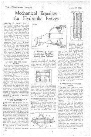
The drawing shows the layout of the mechanical system which is superimposed upon the hydraulic system, not shown. The rod from the handbrake lever pulls, via a bell-crank, on a rod (1) leading to one (2) of the two expanders. The pull is actually applied as a compressive force to the outer casing of a Bowden cable (3), . but, as this is anchored at the far end by a bridge (4) on the back-plate, the pull is divided equally between the two ends of the inner cable, each of which operates one of the expanders.
AN EXPANDER FOR WORN PISTONS
AN expander for prolonging the useful life of a piston is shown in patent No. 561,870, whiai bears the name Ramsey Accessories Manufacturing Corporation, St: Louis, Michigan, U.S.A. The device can be fitted to any normal type of piston when it is desired to correct for wear.
The expander consists oftwo thin cheeks (1) which are located by the gudgeon pin; they are channelled at the lower end to receive the pressure ring (2). The latter is of spring steel which is compressed into a flat oval and then inserted into the channels, where it distorts the piston back into a shape resembling its original state. The two ends of the pressure ring project through a slot in one of the cheeks to receive a secondary hairpin-shaped spring (3), which serves to lock the assembly; it also exerts an additional expansive force.
A GOVERNOR EMBODYING A NEW PRINCIPLE
.CENTRIFUGAL governors are usually operated by a change in engine
speed, but patent No. 562,065 shows a design of governor which is also sensitive to the rate of change of speed; in other words, it gives a quicker response to a sudden acceleration than it would to a gentle increase. The patentees are Joseph Lucas, Ltd., and R. Ifield, both of Great King Street, Birmingham, 19.
The scheme incorporates the conventional mechanism, comprising a fixed collar (1) and a sliding collar (2), both linked to the bob-weights and. separated by a spring (3). Collar 2 is grooved to accommodate the lever (4) of the throttle or other controlled mechanism.
The novelty of the design lies in the fact that the whole of the above apparatus is mounted on a sleeve (5), which acts as a nut on the screwed driving shaft (6). The sleeve is located endways by a pair of springs (7 and 8) and when subjected to violent accelera
tion the, inertia of the mechanism would compress one spring and cause the sleeve to move along the screwed shaft.. This would instantly affect lever 4 by direct movement, without having to wait for the slower action of the bob-weights. When the acceleration ends,the springs would return. the sleeve to its normal central position.
PRODUCER FILTER FOR PEAT OR WOOD FUEL
W/IILLST it is possible to run a gas W producer on almost anything that will burn, each fuel brings its own filtering problems, and patent No.. 562,079 shows cleaning apparatus for use with peat or wood fuel. The
patentee is G.
Hamilton, Red Mills, Clonskeagh, Two methods are employed in series,
first a water bath, then a dry filter. Gas entering pipe 1 is first forced down into a water bath (2) by a. bell (3). Rising on the outside of the bell, the gas passes upwards into a tube (4), whence it is directed through a second water bath (5). Making its exit from the upper end, the gas enters a second casing (6), which is packed with fibrous material such as turf and. finally, leaves via the bottom pipe (7).
A unique feature of the system is that a certain amount of air is admitted to the top of the casing (6) via pipe (8). The result, it is claimed, is to solidify any sticky substances in the gas and deposit them in the filtering medium. Although this admission of air creates an.explosive mixture, risk of fire is said to be absent on account of the two water baths.
A TWO-SPEED GENERATOR • DRIVE
THE wide speed range of a vehicle engine means that, usually, the dynamo does not commence to charge until a fair road speed is attained. To enable the dynamo to operate during periods of.idling is the object of .a twospeed gear shown in patent No. 562,095, by Self-Changing Gear Co., Ltd., and others, Lythalls Lane, Coventry.
The gear consists of three epicyclic elements; they are the .sun pinion on the dynamo shaft, the planet carrier driven by the engine, and the surrounding annulus which can be held or freed as required. In action, if the annulus be held, the dynamo is subjected to an increase in speed. On the other hand; a free annulus creates a straight-through drive, provided that it be prevented from idle over-running. This is achieved by incorporating a . free wheel which couples the annulus to the planet carrier and thus forms a solid drive.
The means for braking and freeing the annuluS may be operated by a hand control, or automatically in accordance with the speed of the engine