


Pressure Build - up in
Page 37
If you've noticed an error in this article please click here to report it so we can fix it.
Img=1----• New Braking System
Fluid Maintained Under Pressure Provides for Power Braking Even With Engine Stationary
wiTITH the introduction of the LockVV heed hydraulic accumulator servo system, yet another important advance has been made in the efficiency of braking arrangements for public-service vehicles, and goods-carrying machines in the heavy classes.
Basically, the principle upon which the system operates is that a quantity of oil is kept under pressure in a special reservoir, and is available for brake operation at any time, irrespective of whether the engine be running or not, An important feature, too is that the amount of fluid used per 'brake application is not, at low speeds, limited by the capacity of the pump.
High-pressure Accumulator
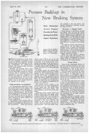
An accompanying illustration shows the general layout of the system, with each component suitably identified, It will be noted that, in the accumulator, there is a floating piston. On one side of this piston air is contained at a pressure of 450-500 lb. per sq. in., and, on the other, the fluid, which is pumped in until a pressure of about 1,200 11). per sq. in. is registered.
The function of the cut-out valve is to control the supply of fluid from the pump in accordance with the pressure in the accumulator. When the pressure reaches about 1,200 lb. per sq, in., the valve comes into operation, and the fluid is diverted to the brake-control valve. Should the pressure in the accumulator fall below the lower operating pressure —usually between 800 and 900 lb. per sq. in.--the valve cuts in, and recharging commences.
In normal service the control valve and master cylinder operate in a similar manner to the continuous-flow servo, but the control valve is mounted in a separate bore, being connected to the pedal and master cylinder by a balance lever. It is arranged to provide for a supply of fluid from the accumulator, should it be required to supplement the normal pump delivery. The normal master cylinder is fed with fluid from the inner compartment of the supply tank, this circuit being independent of the servo circuit. The servo chamber is at the back of the main piston.
Operation of the control valve is as follows:—Fluid from the pump, which is the Lockheed Mark VI of the sevencylindered radial type, enters chamber A (see accompanying drawings), which is connected to the servo chamber, and usually to •the front brakes of the vehicle, which are directly operated by servo pressure. With the master cylin
der coupled to the rear brakes, two entirely independent hydraulic systems are thus provided.
By-pass to Supply Tank
From chamber A, fluid flows through the hollow valve B, past the release valve C, returning to the supply tank via port D. When pressure is applied to the release valve C, by the pedal, the valve commences to shut, and pressure builds up in chamber A until the external pressure applied to C is balanced. Surplus fluid forces its way past C to the supply tank.
If insufficient fluid be delivered by the pump, due to, say, the engine having stopped, valve C pushes the balancedpressure valve B off its seating, and fluid enters chamber A from the accumulator until the external pressure on valve C becomes balanced as before.
When the brake pedal is released, valve C opens fully, and chamber A is then in direct communication with the supply tank, thus allowing the system to breathe in the normal manner,
Pump Drive
Some of the outstanding features of the new Lockheed system are, first, that the pump may be driven from the engine or transmission, and, in the case of trolleybuses, from the traction motor.
The total weight is about 65 lb., which is . claimed to he much less than any servo system of comparable power. Pedal pressure can be made as light as desired, that recommended being 100 lb. per sq. in. for retardation at the rate of 16 ft. per sec.
An interesting point about this system is that the accumulator forms a useful source of power other than for braking. The available fluid under pressure could be utilized for such purposes as power for operating doors, or clutch and steering assistance. The pump absorbs about 2 h.p. at 2,000 r.p.m., when pumping at 1,000 lb. per sq. in. The power absorbed for circulating the oil under ordinary running is negligible.
Working pressure is available immediately the pump starts rotating, and the accumulator.is of sufficient capacity for an unusually large number of .brake applications. The maker is the Automotive Products Co., Ltd., Taehbrook Road, Leamington Spa.