


Engine Behind Cab hi New
Page 42
Page 43
Page 44
Page 47
If you've noticed an error in this article please click here to report it so we can fix it.
Mechanical Horse
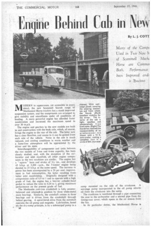
MODERN in appearance, yet accessible in every detail, the new Scammell Scarab range of Mechanical Horse tractors has a much improved suspension system. and 'the components are arranged to give stability and smoothness under all conditions of loading. A more powerful engine has afforded faster acceleration and increased the maximum speed to
over 30 mph. , The engine and gearbox in the new models are built in unit construction with the back axle, which, of course, brings the engine to the rear of the cab. The latter now has a clear floortine, and access to it can be gained from each side of the vehicle. Noise in the cab is much reduced, and cooling conditions in warm weather and a fume-free atmosphere will be appreciated by the driver and his mate, .
Interchangeability of components and units between the two models of 3-ton and 6-ton capaCity, has been closely studied, and, with the exception of the carburetter and inlet manifold, all other engine components in the two machines are similar. The engine has a " square " bore and stroke of 3-&ins., and develops 45 b.h.p. at 3,200 r.p.m., the 3-tonner engine being derated to 25 b.h.p. at the same speed. The increase in power has been accompanied by a 20 per cent, improvement in fuel consumption, the latter resulting from
better inlet manifolding. Originally designed with a compression ratio of 6.9 to 1 and to operate with a high grade of fuel, the engine has a heavier cylinder-head gasket to reduce the ratio to 6.24 to 1, giving maximum performance on the present grade of fuel.
The Meehanite cast-iron crankshaft is fully counterbalanced and retained. in position by three white-metal main bearings. Similarly, the camshaft rotates in three bearings and is driven from the crankshaft through helical gearing. A spiral-bevel drive from the camshaft operates the oil pump and magneto. Lubrication, based on the dry-sump principle, is by a submergedpump in a sump mounted on. the side of the crankcase. A scavenge pump incorporated in the oil pump returns oil from the crankcase into the sump.
The crankcase is ventilated through a pipe connecting the case to the carburetter and a second pipe from the timing-case cover, which opens to the air stream from the fan.
In its particular duties, the Mechanical Horse is
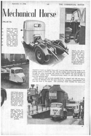
required to warm up rapidly from cold. Care has been taken in the design of the cooling system to achieve this end, and the cooling water from the pump passes through the valve surrounds and returns to the radiator top tank through the aluminium cylinder head. Aluminium-bronze inserts are cast into the head to carry the sparking plugs
Clutch, gearbox and rear-axle assembly form an integral unit with the engine, and may be detached from the main chassis by removing a large-diameter bolt from thc front of the engine This mounting, which includes two heavy-duty
rubber bushes, carries the full torque of the tr.ansmission when driving or braking.
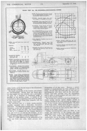
The clutch and gearbox of the 3-tonner and 6-tonner are interchangeable. Second, third and fourth gears are dog-engaged for easy selection, and a power-takeoff point, for a hydraulic or mechanical pump, is provided on the gearbox casing. A feature of the transmission is the arrangement of the drive, the pinion of the final-drive unit being fitted integrally with the gearbox output shaft.
The final-drive unit is a sturdy double-reduction assembly, equipped with a heavy-duty four-pinion differential The differential assembly shares a common lubrication system with the gearbox and a single filler Orifice suffices for the two units • An overall reduction of 9.65 to 1 is standard for the 3-tonner final-drive unit, and 11.23 to I is used for the 6-tonner. A 13.2 to I reduction assembly is available as an alternative for tractors operating with an 8-ton or 10-ton load.
There is a slight difference in the dimensions of the 3-ton and 6-ton rear axles, which. prevents inter changeability of all their parts. However, a certain measure of standardization has been achieved in the design, and the hubs and brake gear of each unit are interchangeable with those used on the semi-trailer Timken taper-roller bearings carry the intermediate shaft in place of double-purpose ball races which were used on the previous model.
The driving axle is secured to the frame through semielliptic springs bearing against slippers carried in brackets attached to the ramp pressing, the slippers and pins of the 3-tonner being interchangeable with those of the larger model. When taking the power and transmission unit from the frame, the assembly is released at the rear by removing the four security bolts under the springs in the slipper bracket.
Girling two-leading-shoe units are fitted to the tractor and semi-trailer of the 6-tonner and single leading-shoe units in the 3-ton model and semi-trailer. With the 3-ton chassis, the brakes are applied mechanically, but on the larger model the semi-trailer brake effort is applied through a Clayton Dewandre
vacuum servo. Balance between the tractor and semitrailer brakes is assured by using a large-diameter control valve. -The brakes on the load carrier are applied through an ingenious mechanism ors the coupling gear. actuating a slipper and bell-crank laser in.ahe centre of the unit.
The front suspension is the same for both models, the normal coil spring being totally enclosed and immersed in oil. Movement of the front wheel is transmitted to the spring through a stamped steel crank. A damping effect is attained by incorporating a fixedsized-orifice valve in the oil bath. As in the earlier model, the steering wheel is connected to the box through a skew gear which is enclosed in a casting together with the steering shaft, the casting being secured to the front tubular cross-members.
Cab Floor is Low To provide easy access to the cab, the frame is downswept at the middle. This provides a low floor line, and the driver is able to step straight off the road into the cab. Care has been taken to plan the controls and seating so that entry can be made from each side of the vehicle. Air is drawn through a duct in the side of the cab to cool the radiator; by this means the tubes are kept free from exterior fouling. Steel is used for the construction of the cab, removable panels being provided in the rear section to make the radiator accessible for maintenance or repair.
On the road, the 6-ton model selected for test exhibited lively acaeleration, and on the first level stretch of road I folind the maximum speed to be 35 m.p.h The machine had a comfortable cruising speed of 25 m.p.h. The improvement in front SIN pension and stability gained from the layolit of the power and transmission unit enabled uneven road surfaces to be taken at speed withOut any signs of
discomfort.
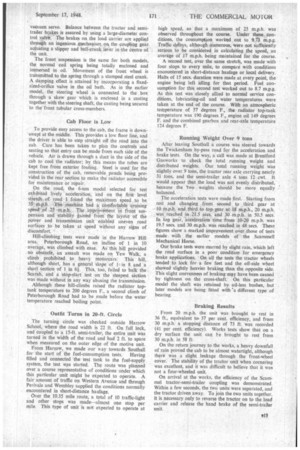
Hill-climbing tests were made in the Harrow Hill area. Peterborough Road, an incline of 1 in 10
• average, was climbed with ease. As this hill provided . no obstacle, an assault was made on Yew Walk; a climb prohibited to heavy motorcars. This hill, although short, has a general slope of 1, in 8 and a short section of 1 in 61. This, too, failed to balk the Scarab, and a stop-start test on the steepest section was made without in any way abusing the transmission. Although these hill-climbs raised the radiator toptank temperature to 200 degrees F., a second climb of Peterborough Road had to be made before the water temperature reached boiling point.
Outfit Turns in 20-ft. Circle The turning circle was checked outside Harrow School. where the road width is 22 ft. On full lock, and coupled to a 15-ft. semi-trailer, the entire unit was turned in the width of the road and had 2 ft. to spare when measured on the outer edge of the motive unit.
From Harrow, we made our say towards Southall for the start of the fuel-consumption tests. Having filled and connected the test tank to the fuel-supply system, the test was started. The route was planned over a course representative of conditions under which this particular unit might be expected to operate. A fair amount of traffic on Western Avenue and through Perivale and Wembley supplied the conditions normally encountered in short-distance haulage.
Over the 10.35 mile route, a total of 10 traffic-light and other stops was made—almost one stop per mile. This type of unit is not expected to operate at high speed, so that a maximum of 25 m.p.h. was observed throughout the course. Under these eonditions, the consumption worked out to 9.7) m.p.g. Traffic delays, although ournerous, were not sufficiently serious to be considered in calculating the speed, an average of 17 m.p.h. being maintained for the course.
A second test, over the same stretch, was made with four stops to every mile, to compare with conditions encountered in short-distance haulage or local delivery. Halts of 15 secs, duration were made at every point, the engine being left idling for that period. Fuel consumption for this second test worked out to 8.7 m.p.g. As this test was closely allied to normal service conditions, lubricating-oil and water temperatures were taken at the end of the course. With an atmospheric temperature of 57 degrees F., the radiator top-tank temperature was 190 degrees F., engine oil 149 degrees F. and the combined gearbox and rear-axle temperature 114 degrees F.
Running Weight Over 9 tons After leaving Southall a course was steered towards the Twickenham by-pass road for the acceleration and brake tests. On the way, a call was made at Brentford Gasworks to check the total running weight and distributed weights. Our total running weight was slightly over 9 tons, the tractor rear axle carrying nearly 31 tons, and the semi-trailer axle 4 tons 12 cwt. It would appear that the load was not evenly distributed, because the 'two weights should be more equally balanced.
The acceleration tests were made first. Starting from rest and changing from second to third gear at 10 itp.h. and third to top gear at 18 m.p.h., 20 m.p.h.
was reached in 21.5 secs, and 30 in 50.5 secs. In top gear, acceleration time from 10-20 m.p.h. was 19.5 sees. and 30 m.p.h. was reached in 48 secs. These figures show a marked improvement over those of tests made with the earlier models of the Scarnmell
Mechanical Horse. • Our brake tests were marred by slight rain, which left the road surface in a poor condition for emergency brake applications. On all the tests the tractor wheels tended to lock for a few feet and the off-side wheel showed slightly heavier braking than the opposite side. This slight unevenness of braking my have been caused by tightness on the cross-shaft. On this particular model the shaft was retained by oil-less bushes, but later models are being fitted with 'a different type of bea ring.
Braking Results From 20 m.p.h. the unit was brought to rest in 36 ft., equivalent to. 37 per cent. efficiency, and from 30 m.p.h. a stopping distance of 73 ft. was recorded (41 per cent. efficiency). Works tests show that on a dry surface the unit can be brought to rest from 30 m.p.h. in 58 ft On the return journey to the works, a heavy downfall of rain proved the cab to be almost watertight, although there was a slight leakage through the front-wheel cover. The stability of the tractor unit when cornering was excellent, and it was difficult to believe that it was not a four-wheeled unit.
On arrival at the works, the efficiency of the Scammel tractor-semi-trailer coupling was demonstrated. Within a few seconds, the two units were separated, and the tractor driven away. To join the two units together, it is necessary only to reverse the tractor on to the load carrier and release the hand brake of the semi-trailer unit.