


Scientifically Designed Engine Mounting
Page 36
If you've noticed an error in this article please click here to report it so we can fix it.
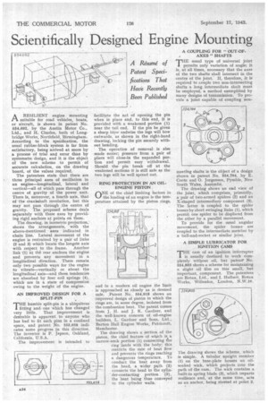
ARESILIENT engine mounting suitable for road vehicles, boats, or aircraft, is shown in patent No. 554,692, by the Austin Motor Co., Ltd., and H. Charles, both of Longbridge Works, Northfield, Birmingham: According to the specification, the usual rubber-block system is far from satisfactory, being arrived at more by a process of trial and error than by systematic design, and it is the object of the new, scheme to permit of accurate calculation, on the drawing board, of the values required.
The patentees state that there are three principal axes of oscillation in an engine—longitudinal, lateral and vertical—all of which pass through the centre of gravity of the power unit. There is, moreover, a fourth axis, that of the crankshaft revolution, but this may not pass through ,the centre of gravity. The proposed scheme deals separately with these axes by providing rigid anchors at points on them.
The drawing, in isometric projection, shows the arrangements, with the above-mentioned axes indicated in chain line. Lateral movement of the engine is restrained by a pair of links (2and 3) which locate the longest axis with respect to the frame. Another link (1) at the rear anchors the engine and prevents any movertent in a longitudinal direction. There remain only two possible ways for the engine to vibrate—vertically or about the longitudinal axis—and these tendencies are absorbed by four coil springs (4), which are in a state of compression owing to the weight of the engine.
AN IMPROVED DESIGN FOR A SPLIT-PIN
THE humble split-pin is a ubiquitous fitting and one which has changed very little. That improvement is desirable is apparent to anyone who has had to fit such pins in a confined space, and patent No. 553,658 indicates some progress in this direction. The inventor is P. Jepson, Oakland, California, U.S;A.
The improvement is intended to facilitate the act of opening the pin when in place and, to this end, it is provided with a weakened portion (I) near the tail end. If the pin be given a sharp blow endwise the legs will bow outwards, as shown in the right-hand drawing, locking the pin securely without bending.
The operation of removal is also made easier; pressure from a pair of pliers will close-in the expanded portion and permit easy withdrawal. Should the pin break off at the weakened sections it is still safe as the two legs will be well spread out.
RING PROTECTION IN AN OILENGINE PISTON rINE of the chief limiting factors in %--1 the loading of an engine is the temperature attained by the piston rings, and in a modern oil engine the limit is approached as closely as is deemed safe. ,Patent No. 554,918 shows an improved design of piston in which the rings are in some degree, isolated from the combustion heat, The patent comes from J. H. and J. K. Gardner, and the well-known concern of oil-engine builders, L. Gardner and Sons, Ltd., Barton Hall Engine Works, Patricroft, Manchester.
The drawing shows a section of the piston, the chief feature of which is a narrow-neck portion (1) connecting elle ring lands with the body; this restricts the rate of heat flow and prevents the rings reaching a dangerous temperature. To conduct the heat away from the head, a wider path (2) connects the head to the cylinder-contacting portion (3), the heat being thus conveyed to the cylinder walls. A COUPLING FOR "OUT-OF. AXES " SHAFTS THE usual type of universal joint 1 permits only variation of angle; it is, at all times, necessary that the axes of the two shafts shall intersect in the centre of the joint.. If, therefore, it is required to couple two non-intersecting shafts a long intermediate shaft must be employed, a method exemplified by many designs of transmission. To provide a joint capable of coupling non meeting shafts 'is the object of a design shown in patent No. 554,794, by E. Coote and 0. Jorgensen, Pymble, New South Wales, Australia.
The drawing shows an end view of the joint, which comprises, primarily, a pair of two-armed spiders (2) and an X-shaped intermediary component (3). The latter is coupled to the spider bosses by short swinging links (1), which permit one spider to be displaced from the other by a parallel movement.
To provide for the usual 'angular movement, the spider bosses. are coupled to the intermediate member by a ball-and-socket or similar joint.
A SIMPLE LUBRICATOR FOR IGNITION CAMS
THE cam of an ignition interrupter is usually destined to work completely without oil, but pa.tenr No. 554,803 shows a scheme for maintaining a slight oil film on this small, but important, component. The patentees are Rotax, Ltd., and I. Hulbert, Rotax Works, Willesden, London, N.W.10.
The drawing shows the scheme, which is simple. A tubular upright member (1) on the base-plate houses an oilsoaked wick, which projects into the path of the cam. The wick contains a built-in spring blade (3), which imparts resilience and, at the same time, acts as an anchor, being riveted at point 2.