


Sealing Sliding Joints
Page 84
If you've noticed an error in this article please click here to report it so we can fix it.
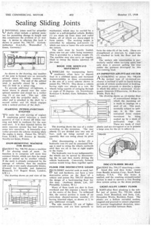
UNIVERSAL joints used for propeller shafts often include a splined member for permitting change in length and this complicates the problem of oil scaling. A device to alleviate this fault is shown• in patent No. 79,8,737. (Gelenkwellenbau G.m.b,H., Westendhof 7, Essen, Germany.)
As shown in the drawing, one member of the joint is formed into an internally splined sleeve (1) which receives the • propeller shaft. The end of the splined joint is partially .closed by a rubber seal (2) held in a metal ring.
To provide additional oil-tightness, a metal sleeve is placed over the outer splined member and closed by a rubber ring (3) at one end.. This cari slide axially with the propeller shaft, The other end is attached to the shaft by a second rubber seal (4) which engages with a necked portion of the shaft.
STARTING PETROL-INJECTION " ENGINES
To assist the cold starting of engines employing petrol injection, a small quantity of fuel is •drawn off While running and held in .readiness for the next cold start. It is then injected before the main injection sYstern• has had time to come into operation. A -bimetallic controller preventsthe scheme Working while the engfne is warm. Patent No. 797,657, from S.I.B.E., 190 Avenue le Neuilly, Neuilly-sur-Seine, France.
SNOW-REMOVING MACHINE FOR ROADS
PATENT No. 798,792 shows a machine for clearing roads of snow. Its function is to compress soft snow into compact blocks, which can then be swept aside or picked up by another vehicle. If the snow is, already compacted by the passage of vehicles, then the machine will crack it into easily disposable blOcks. (Council for Scientific and Industrial Research, 5-11 Regent Street, London, S.W.1.)
The drawing shows an end view of the mechanism, which may be carried by a trailer or a self-propelled vehicle. ROHM ) are made up from discs and radial blades, all of which are sharp-edged to form cutters. The working height is • controlled by adjusting jack-screws i 2) which can raise or lower the axle carrying the cutters.
The units must be heavily loaded, about one ton per roller being necessary. This is provided by a ballast weight (3). The machine may also carry an angular blade to sweep the blocks sideways off • the road.
BOGIE FOR SIDEWAYS MOVEMENT "
VEHICLES for transporting heavy machinery often have to deposit load in a confined space, and increased manceuvrability in these circumstances is the aim of a novel scheme shown in patent No. 799,553. This shows a vehicle
having eight rear wheels in row, the wheels being capable of swinging through an angle of 90 degrees. (A. Nooteboom, Kerklaan 9, Kethel, Gem. Schiedam, Holland.) • The drawing shows the rear of a trailer according to the invention. The rear wheels (1) are divided into two sets of four, each set being carried on an assembly that can swing about its pivot (2).
After disconnecting a tie-bar (3) a hydraulic ram (4) and its associated linkage is used to swing the wheels outwards until they are all in line at right angles to the frame.
The hydraulic ram is not indispensable; the wheels can be spread by disconnect ing the tic and then slowly driving the vehicle backwards. Conversely, forward motion would brine them together again.
FLOOR FOR DESTRUCTIVE LOADS IIQUILDERS' material such as sand, bat.l) last and hardcore, can have a very destructive action on the floor of a vehicle and patent No. 799,535 discloses the design of a hard-wearing floor for this duty. (Anthony Hoists, Ltd., 107 Piccadilly, London, W.I.) Many of these loads are shot in from overhead and this imposes a heavy load on the centre of the floor. To withstand this, the central portion is made of an extra-deep channel-section member (1) having inturned edges, as shown at 2, to give additional strength.
The side members (3) are of lighter construction, and are bent upwards to form the sides (4) of the body. These are strengthened at intervals by angle-irons (5) attached to both the floor and the sides.
The unitary side construction is particularly useful when carrying sand; 'not only does it prevent spilling but also resists the pressure developed by this free-running load. _
AN IMPROVED AIR-INTAKE FILTER )k CCORDING to patent No. 798,458 ri the normal type of oil-betted .air cleaner is inclined to spill its liquid diking periods of violent acceleratioti or braking. The patent proceeds to describe a design in which this defect is minimized. (Cornpagnie Generale D'Electricite, 54 Rue La Boetie, Paris 8e.) The drawing shows an oil-wetted filter of conventional design in which the .incoming air is made to impinge. on a pool of oil. This pool, normally subject to spillage, is in this case .restrained from violent movem ent by being soaked up by a stack of perforated rings (1). These are made of vinyl lastic.and are corrugated so as to present a large area for the oil to adhere to.
DISC-CUM-SHOE BRAKE
DATENT No. 799,157 describing a com
bined disc and shoe brake comes from Bendix Aviation Corp., South Bend, Indiana, U.S.A. The disc brake is applied, and the resulting circurriferential motion is used to operate a free floating shoe system acting on the drum portion.
LIGHT-ALLOY LORRY FLOOR IGHT-alloy floor planking is the subject of patent No. 799,166, which comes from Bonallack and Sons, Ltd., Nevendon Works, Basildon, Essex, The planks are a hollow extruded section, tongued and grooved to ensure alignment. To prevent longitudinal deviation, interlocks are provided between them.