


Resilient Mounting for Tankers
Page 36
If you've noticed an error in this article please click here to report it so we can fix it.
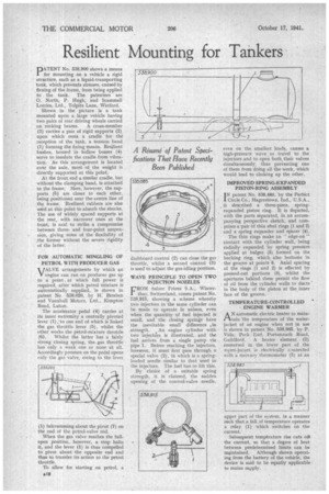
PATENT No. 538,900 shows a means for mounting on a vehicle a rigid structure, such as a liquid-transporting tank, which prevents stresses, caused by flexing of the frame, from being applied to the tank. The patentees are O. North, P. Hugh, and Scammell Lorries, Ltd., Tolpits Lane, Watford.
Shown in the picture is a tank mounted upon a large vehicle having two pairs of rear driving wheels carried on rocking beams. A cross-member (3) carries a pair of rigid supports (2) upon which rests a cradle for the reception of the tank, a tension hand (1) forming-the fixing means. Resilient bushes, housed in hollow bosses (4) serve to insulate the cradle from vibration. As this arrangement is located over the axle, most of the weight is directly supported at this point.
At the front end a similar cradle, but without the clamping band, is attached
• to the frame. Here, however, the supports (5) are closer to each other, being positioned near the centre line of the frame. Resilient rubbers are also used at this point to absorb the shocks. The use of widely spaced supports at the rear, with narrower ones at the front, is said to strike a compromise between threeand four-point suspension, giving some of the flexibility of ,the former without the severe rigidity of the latter.
FOR AUTOMATIC MINGLING OF PETROL WITH PRODUCER GAS
ViALVE arrangements by which an V engine can run on producer gas up to a point at which full power is required, after which petrol mixture is automatically supplied, 'is shown in patent No. 539,020, by H: Biraben and Vauxhall Motors, Ltd., Kimpton Road, Luton.
The accelerator pedal (4) carries at its inner extremity a centrally pivoted lever (1) to one end of which is linked the gas throttle lever (5), whilst the 'other works the petrol-mixture throttle (6). Whilst the latter has a fairly strong closing spring, the,gas throttle has only a weak one or none at all. Accordingly pressure on the pedal opens only the gas valve, owing to the lever (1) fulcrumming about the pivot (7) on the end of the petrol-valve rod.
When the gas valve reaches the fullopen position, however, a stop halts it, and the lever (1) is thus compelled to pivot about the opposite end and thus to transfer its action to the petrol throttle.
To allow for starting on petrol, a dashboard control (2) can close the gas throttle, whilst a second control (3) is used to adjust the gas-idling position.
WAVE PRINCIPLE TO OPEN TWO INJECTION NOZZLES
FROM Sulzer Freres S.A., Winterthur, Switzerland, comes patent No. 538,915, showing a scheme whereby two injectors in the same cylinder can be made to operate in unison, even when the quantity of fuel injected is small, and the closing springs have the inevitable small difference in
strength. An engine cylinder with two injectors is illustrated, and the fuel arrives from a single pump via pipe 1. Before reaching the injectors, however, it must first pass through a special valve (2), in which is a springloaded needle similar to that used in the injectors. The fuel has to lift this.
By ' choice of a suitable spring strength, it is claimed-, the sudden opening of the control-valve needle,
even on the smallest loads, causes a high-pressure wave to travel to the injectors and to open both,their valves simultaneously, thus preventing one of them from doing all the work, which would lead to choking up the other.
IMPROVED SPRING-EXPANDED PISTON-RING ASSEMBLY
JN patent No. 538,685, by the Perfect
Circle Co., Hagerstown, Ind., U.S.A., is described a three-piece, springexpanded, piston ring. It is depicted, with the parts separated, in an accompanying perspective sketch, and comprises a pair of thin steel rings (1 and 2) and a spring expander and spacer (4).
The thin rings make an " edge-on " contact with the cylinder wall, being radially expanded by spring pressure applied at bulges (5) formed on the backing ring, which also bottoms in the groove at points 6. Axial spacing of the rings (1 and 2) is effected by pressed-out portions (3), whilst the apertures behind these permit the flow : of oil from the cylinder walls to ducts in 'the body of the piston at the inner face of the groove.
TEMPERATURE-CONTROLLED • ENGINE WARMER
AN automatic electric heater to maintain 'the temperature of the waterjacket of an engine when not in use is shown in patent No. 538,985, by P. Vida, Park End, Portsmouth Road, Guildford. A heater element (2) immersed in the lower part of the water-jacket is electrically cennected with a mercury thermometer (3) at an
upper part of the system, in a manner such that a fall of temperature operates a relay (1) which switches on the current.
Subsequent temperature rise cuts oil the current, so that a degree of heat between predetermined limits can be maintained. Although shown operating from the battery of the vehicle, the device is said to be equally applicable to mains supply.