


ELECTRICALLY DRIVEN ON EVERY WHEEL.
Page 20
Page 21
If you've noticed an error in this article please click here to report it so we can fix it.
A New Production which is Claimed to be Capable of Operation on Bad Ground and Slippery Surfaces and to be Useful for Municipal Refuse Collection.
THERE has been in operation for a few months by the Cleansing Department of the Corporation of the City of Birmingham a powerful electric vehiclotmanufactured by
Electromohile, Ltd., of Prospect Works, Otley, Yorks., the novel point about its design being the fact that the drive is taken to every wheel, each one having its own electric motor.
The aim of this arrangement is to secure a very powerful tractive effort, one which obviously should be considerably greater than that given by the usual type of drive to two or more axles, where two, or perhaps three, differentials hfive to be employed. Thus, there is on obvious reduction of possible loss through friction, whilst a further merit 'which is claimed for the drive is that, should one wheel sup, it in no way affects any of the others—hence a four-wheel electrically driven vehicle should be capable of being worked on extremely A high maximum speed is not necessary for a vehicle engaged on refuse collection, home 15 m.p.h. is the calculated maximum with fully charged batteries. The vehicle generally is operated at 10 m.p.h., and its radius per charge is 30 miles, but this distance has not yet been given to us officially, and, again, is one of the factors to be reported upon later.
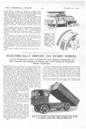
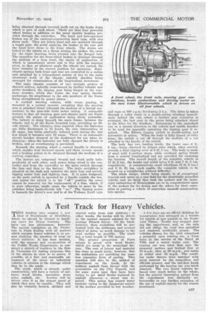
The body is of considerable capacity, . being 12 ft. long by 6 ft. 11 ins, wide and 3 ft. high, each dimension being taken inside. It has a capacity of 5 tons, but V tons can he comfortably carried, The cab is capacious and will seat five men, including the driver,. and gives ample protection from the weather, the upper panel of the driver's half of the windscreen being made to hinge outward. An extremely good tipping angle is provided, as can be judged from our illustrations.. To deal now with the driving mechanism. The four motors are each of 21 h.p. and their method of mounting is clearly shown in the drawing which accompanies this description. Each axle is of the open-girder type, being connected by tie rods for the rear axle, whilst the steering pivots of the front, axle are arranged on the tpp and bottom of the motor casings for the front axles. The stub axles are mounted on these casings and attached by bolts, the wheels being further mounted on the stub axles with Timken bearings of generous size.
The drive is taken from each motor to its wheel by compound gearing with a ratio of, roughly, 20-1, the final drive being obtained through internal teeth cut on the brake drum which is part of each wheel. -• There are thus foUr powerful wheel brakes in addition to the usual electric braking provided through the controller. The hand and foot-operated brakes are of the external-contracting band type, with two shoes each. They are fabric lined and are operated through a toggle gear, the pedal applying the brakes at the rear and the hand lever those to the front wheels. The drums are bolted to the wheels on a flange joining the spokes, the races for the taper bearings being pressed into the flanged hub. The operation for the front-wheel brakes is obtained through the medium of a long lever, the centre of application of which is immediately above and in line with the steering pivot, so that, at whatever angle the wheels are turned, the lever remains in the correct -position for operation. Semielliptic springs both front and rear are controlled by a radies. arm attached by a triangulated system of ties to the main structural work of the chassis, suitable shackles being arranged for compensation of the longitudinal movement.
The main chassis consists of two straight girders of channel section, suitably cross-braced by further tubular and girder members, the tipping gear being hinged on the rearmost member, which also forms the rear spring shackle anchorage, its attachment to the side members of the frame being strengthened by gusset plates.
A. vertical steering column, with • worm gearing, is mounted in a normal 'manner, excepting that the steering arm is attached direct (through the medium of a lateral connection) to the near-side front motor casing. A noticeable feature is that all steering gear and chassis parts are Enots greased, the points of application being fairly accessible. The battery is slung beneath the main frame, between the wheels, and is of the Exide Ironclad type, providing an 80volt circuit. The charging time required when the batteries are fully discharged is 12 hours, the rate commencing at 65 amps., but being gradually reduced until during the last few hours it becomes only 10 amps. There is an automatic cirenit breaker situated on the dashboard for use when recharging; when, the batteries are fully charged the circuit is broken, and so overcharging is prevented.
Beneath the steering wheel a centrol handle is situated, which enables four forward speeds and three reverse speeds and a braking action to be obtained through the medium of a vertical controller.
The motors are compound wound and work quite independently of each other, each motor being wired to the controller and from the controller to the main switch through the fuse and then to the battery. The Main switchbox is situated on the dash cud contains the main fuse and switch, tipping motor fuse and lighting fuse. It is quite foolproof, as the main switch is operated by a handle outside the hex, and unless the switch is in the "o" position the cover cannot be removed. for the replacement of a fuse, which, if it were otherwise, might cause the vehicle to move by the .switches being inadvertently left "on." The tipping motor is beneath the driver's seat and is of the Todman Ityall type
and runs at SOO r.p.m. developing 2 h.p. The drive is taken through a railer chain to a double-acting windlass immediately behind the cab, where a further gear reduction is arranged, the last gear in the series being attached direct to the drive for the windlass. Extensions to the maiushaft run in a lateral direction to the vehicle and enable handles to be used for manually operating the tipping gear if re quired. The Ellison tipping switch is double-acting and automatic in action. When the body is fully tipped, or fully hems, the switch is cut off through the medium of a rod attached to the handle of the switch.
The body has two loading levels, the lower one--4 it. 9 ins.—being, obtained by hinged sides which, when erected, provide a final tipping level of 6 ff. 3 his. The body is made of steel with. L-.section stays, while overhead spring blinds from a central longitudinal rail are provided for enclosing the interior. The overall length of the complete vehicle is 17 ft. 5 ins., the height and width being 8 ft. and 7 ft. 5 ins. respectively. A comparatively small wheelbase (9 ft. 9 ins.) and 5 ft. 61 ins, track enable the complete vehicle to be located on a weighbridge without difficulty. The whole design, whilst being simple, is of exceptional interest and opens up a new field for the electrically propelled vehicle, and we think that both the makers and the municipal authorities of Birmingham are to he congratulated upon it, the makers for its design and the others for their enterprise in putting a vehicle of somewhat unusual construction into service.