


Swash-plate Injection Pump
Page 52
If you've noticed an error in this article please click here to report it so we can fix it.
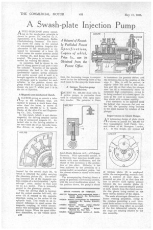
AFUEL-INJECTION pump operating on the swash-plate principle is shown in patent No. 426,316 by F. Egersdtirfer, of 5, Goethepark, BerlinCharlottenburg, Germany. The drawing shows the pump in the neutral or non-pumping position. Angular displacement of the swath-plate is obtained by movement of a lever (2) which turns the carrier member about
• a bearing (3), and forms the output control. The pump is, of course, controlled by varying the stroke.
In operation, fuel is drawn in via port 6, along groove 5 and port 4 into the cylinder. Rotation of the spindle compresses the fuel in the cylinder (presumably against spring pressure) and carries around port 6 until it is brought opposite its discharge port (7). A discharge port is provided for each cylinder; in the position shown the pump would be taking in fuel for discharge via port 7, whilst port 1 is in the act of injection.
A Magnetic.cum-mechanical Clutch.
CAA CLUTCH giving as smooth a takeup as the hydraulic type, yet claimed to possess a much lower drag value than the latter, is shown in patent No. 426,368 by G. T. SmithClarke, of the Alvis Car and Engineering Co., Ltd., Coventry.
In this clutch (which is not electromagnetic) the driving member carries a ring of permanent magnets (1). Attached also to the driving member is the sun-wheel (4) of an epicyclic train. The driven, or output, member is formed by the central shaft (3), to which is attached the spider carrying the planetary pinions (2). The revolving armature (5) of the magnetic system consists of a short-circuited "squirrel-cage" rotor, similar to that used on an ac. motor. This is internally geared to the planetary pinions.
When the driving shaft is turning, and the output member held still, the rotor (5) is rotated in the opposite direction, owing to the action of the epicyclic train. This results in an increased difference in speed across the magnetic coupling, in which circumstance this mechanism will transmit its greatest torque. When the speed difference diminishes, as the vehicle speed 542 rises, the decreasing torque is compensated for by the increasing share of the load taken by the epicyclic train alone.
A German Injection-pump Modification.
pATENT No. 426,393 deals with injection pumps, in particular those used in conjunction with open injection nozzles. The patentee is Hum
boldt-Deutz Motoren A.G., of Cologne, Germany. With open-ended nozzles, it is desirable that injection should commence with some suddenness, and the object of this invention is the production of this effect. Hitherto, it has been achieved by the provision of a spring-loaded accumulator piston, but the present scheme is stated to be much simpler.
The accompanying drawing shows a pump of generally conventional outline, with the novel modification added. In the position shown, the pump is about to commence the pressure stroke, and the invention lies in the position of the edge 2. This, it will be noticed, is slightly below the level of the injection port (1), so that when the plunger rises the oil is momentarily under an extremely high compression, owing to its being confined in a closed space. So soon as the port is uncovered, injec.. tion starts with extreme rapidity.
Fuel continues to be injected until the helical edge uncovers the port on the left, the quantity being variable in the usual manner by rotation of the plunger.
Improvements in Clutch Design.
AN interesting design of plate clutch is shown in patent No. 426,407 by New Consolidated Gold Fields, Ltd., and others, of 49, Moorgate, London, E.C. In this design, one normal set of friction plates (3) is employed, whilst the corresponding surfaces comprise a number of steel discs (2) mounted on pins (1) so that they are free to revolve until tightly pressed between the two annular plates (3) which grip the crescent-shaped portion of each, remote from the clutch centre, the disc pivots being carried on the inner driven member of the clutch.
The main advantages claimed are:— Better wearing properties, owing to the rotation presenting a cool, lubricated fresh surface to the friction rings, and a lessened drag effect on account of the low differential velocity when the rings are rotating relative to the disc assembly.