


OVERHAULING THE NAPIER.
Page 22
Page 23
Page 24
Page 25
If you've noticed an error in this article please click here to report it so we can fix it.
THE PRODUCTION of the 30-45 cwt. Napier chassis, with which we deal 'n this article, was commenced between 1914 and 1915, and a large number was sold to the Government, as well as to private users. Many of the Government vehicles have now been converted to -civilian use and are giving extremely satisfactory service.
If the vehicle has been carefully treated a complete overhaul should not be required before it has completed 60,000 miles, that is to say, the equivalent of two years' hard work.
Dismantling.
Before the actual dismantling is commenced, the body should be removed and the chassis thoroughly cleaned.
As is usual, it is better to commence dismantling at the front end of the chassis. Disconnect the water connections and remove the radiator. Unscrew the petrol pipe connection and detach the exhaust pipe from its branch. Break the flexible joint at the rear of the clutch by removing three of its bolts, and remove the starting handle cross-member. A suitable sling should now be attached to the engine, care being taken that the ropes do not foul the carburetter, water pipe, etc., and the weight of the engine should be taken by a tackle capable of lifting at least 12 cwt. The bolts holding the .engine may now be withdrawn, and the engine lifted clear of the frame.
The gearbox is suspended by four bolts, and the best way to remove it is to take out these bolts and lower the box into a trolley, after having removed the change speed and footbrake connections.
At the rear end of the eardan shaft is a plunger joint, and if the leather cover .sad front plate of this be removed the shaft can be withdrawn. The rear axle can be left in position if thought advisable, but as the springs will probably require attention it is best to remove the axle complete with its springs.
Overhauling the Engine.
Empty the ail out of the sump and remove the latter. Unscrew the valve caps and take off the water connections, magneto, and timing ease cover. Before removing the timing gear chain it is advisable to check the timing so that when re-assembling the engine it can be timed:correctly. Take off the bigend and main bearing caps, and lift out the crankshaft, connecting rods, and pistons. Clean out the oil pipe in the crankcase by squirting paraffin through it, examine the camshaft for wear on its bearings ; these are of east iron, the centre one being held in position by a setscrew. The camshaft is located by its front bearing.
At the rear end of the crankshaft front journal are two locating pegs holding a hardened steel thrust washer, which bears against the flanges of the big end brasses. A similar washer is positioned at the front end of the journal and is held by the timing pinion key. If the crankshaft journals are worn oval the crankshaft should be reground, or, if the journals are only slightly scored, they can be lapped by hand.
Care should be taken to clean out the crankshaft oilways by removing the caps which are situated in the webs at the ends of each crankpin. These should be replaced very carefully in order to avoid oil leakage. The tappets can be removed by taking off the spider clamps, when the guides can be lifted out complete with the tappet rollers. The latter and their pins should be examined and replaced if worn.
The whole of the oil pump assembly oan be removed by unscrewing the three holding-down nuts ; incidentally, it is unnecessary to remove these in order either to clean the strainer or to examine the by-pass valve. These operations can be carried out by removing the large plug in the cover for the strainer, . and the tall plug for the by-pass. The short plug is for inspecting the pump drive. The middle locating flange of the pump 'body is cut away to clear the skew gear on the camshaft. Dirt may lodge under the bypass valve, thus preventing oil from circulating, as it merely flows back into the pump. The whole of the pump and the oil circulation system should therefore be kept scrupulously clean. The skew gears have a very long life, but should, of course, be examined.
The pump spindle bashes may possibly require renewing, but this is unlikely. The pump pinion cover is a die casting, and if the pinions in it are slack the whole cover, which is quite cheap, should be replaced.
The water pump glands should be repacked with spun lead. The gland nut is circular and is provided with radial holes by which it. is turned. A locking plate holds it in position. Yellow grease should never be employed for lubricating the water pump. The best lubricant for this is white ;tallow.
The silent chain .driving the timing gears can be adjusted through a special orifice in the timing gearcase cover, but during overhaul it is better to adjust
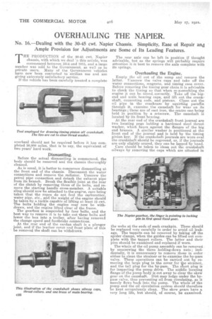
it with the., cover off. Adjustment is provided by swinging round the magneto and water pump .driving pinion ; • this is' done by unscrewing the. setscrew carried by the bracket holding this pinion. The head of the setscrew bears against a flange cast in one with the timing ease, and after a,djustiitent the setscrew should be locked firmly by the-nut provided. Before making any.adjustinents the nuts onthe studs holding the bearing housings. on each side of the driving pinion must be slackened off. The studs are in grooves so that. the hous.ing-s can be moved without Jamming (against them. After. making adjustments, these housing nuts should again be tightened. Allow a total lift 'On the silent•chasin of about The clutch. iS of the •single plate type, and the plate floats between two • rings of Ferodo. In the . crankshaft spigot is a „small hardened thrust button, and in the clutch shaftis an adjusting screw with 2, left-hand thread. At the end of this adjusting screw is another thrust button which bears against the button in the crankshaft spigot. The movement of the clutch centre, which is secured to the clutch shaft, is restricted by the adjusting screw. Over the hexagon of the latter fits a brass locking sleeve, which is itself secured by a spring plunger.* The latter must be pulled up and turned round to free the locking sleeve, which is held up to its work by a spiral spring.
The clutch has 10 pressure springs, all of the spiral type, and the presser plate, face plate. and flywheel are all marked for positioning to ensure correct balance when re Plate to see that it is not distorted. This sometimes occurs owing to overheating caused by faulty driving. if adjustment is required, tue setscrews Of the -operating fingers, of which there are five, can be screwed in or-out. Care must be taken to see that all are adjusted to the same amount, and they should have a, clearance of about
Dealing with the Gearbox.,
Special attention should be paid to the selector gear. Make certain that the locking ball and spring are free • -also that if the cap is re-moved it is replaced so that the spring locking ring is correctly positioned, otherwise, the cap, spring and ball may drop out. Tho operating collars, which are of phosphor-bronze, are liable to wear, and if much worn must be replaced. There is seldom any wear on the fork pins.
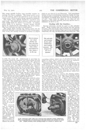
Attention should he paid to the Oil retainers at the back and front. The-se are cast iron rings floating on four locating pins and pressed up to their workby four small spiral springs. The oil retainer covers are faced off and thevcast-iron rings bear on these faces. The gearshafts are on roller bearings and are positioned endwise by hardened steel plates which. butt against the ends of the rollers. To dismantle the box, remove the :driving spider, the front oil retainer cover and the footbrake drum and oil retainer at the rear. The roller platen at each end can now be taken off. Unscrew the locking pin in the first-speed fixed gear. This pin is held by a wire which should be replaced when re-assembling. The main shaft can then be drawn right out, leaving the gears in the box. Take particular care to remove all the rollers from the races, and to put them aside. The main shaft is s•pigoted into the primary shalt, and the latter must now be withdrawn. To do this, remove the four nuts which told the primary shaft housing in position, the whole assembly can then be
withdrawn an d the primary shaft removed.
To remove the layshaft, undo the locking pin in the constant mesh wheel.after removing its holding wire as in the case of the other locking pin, remove the end bearing caps and the nut at the front end of the shaft. The latter can then b e withdrawn while its gears drop into the box. If the rollers are worn,
these, being loose, can be replaced without difficulty.
When reassembling it is important to replace the gearbox lid correctly, as the oil in the box is swirled round by the gears and, if the lid is positioned wrongly, the oil will be thrown through the air vent. This Will be prevented if the lid is ,so arranged that the air vent .1s at the rear of the box. Greaseproof paper washers should be used for bearing oaps, and brown paper or thin fibre for the gearbox cover.
When setting up in the frame, the gearbox can be aligned with the engine by adjusting the front suspension bolt. Sideways adjustments can be made by the use of packing washerseto locate the position of the suspension bolt on the gearbox pin.
At the rear of the gearbox is a pin type 'universal joint fitted with hardened steel bushes. Between the collars on these bushes and the centre of the star piece are bronze washers, between which and the bushes are V-lea,ther rings which fit into recesses cut in the bush fan-gee and brass washers. The joint requires some little manipulation in order to assemble these various parts into position as the leather washers must be compressed tightly between the flanges and washers in order entirely to prevent the loss of any lubricant.
Thedriving cap on each rear -wheel is provided with two tapped holes for the insertion of forcing-off bolts. The axle tube nuts are each provided with two keys held' in position by stout split pins. By removing the split pins and keys and inserting a piece of flat steel into the keyways, the nut -oan be unscrewed. There are six key grooves in each axle tube ; to allow for adjustment and to take up end play on a wheel the nut should be screwed up to the next keyway. If the one-sixth of a revolution provided for in this manner is too great or too little, adjustments in between can be made up by packing washers.
As Timken roller bearings are employed for all the wheels, the greatest care should be taken in their ad
justment. The correct way is to screw the bearings up. until they are tight and then to, slack back the adjusting nuts until there is a just perceptible rock on the wheel when it is shaken by means of the spokes..
The differential shafts are tapped, at the ends for the insertion of bolts to assist in withdrawing them. The differential is provided with roller bearings on each side, lateral play being taken up by ball thrusts. To adjust the differential, first set the worm into the correct position, for which purpose the double thrust bearing at the. rear of the worm can be adjusted by packing washers, after removing
the rear cap and -worm shaft nut.
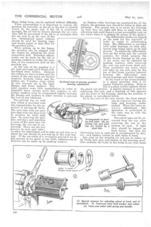
Then, centralize the worm wheel and take up any aide play by the use of thin brass washers inserted between the. differential case thrust bearings and their housings. At the front of the worm 'housing is a gland provided with I in.
square Palmetto packing: Next to this is a plain washer against which the gland nut presses. A special spanner is used for
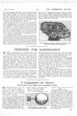
tightening this nut, and a drawing of this spanner and the front, of the housing, showing the position of the gland, is reproduced below. As in the case of the rear wheels, the front wheels can be removed, leaving the hubs and bearings undis turbed. When the latter requir e adjustment, this operation is performed in the same way as with the rear wheels.
The swivel pins can be ex tracted from the top, after removing the nut at the bottom of each. If tight they should be tapped up from below. See that the lubricating hole in each pin is unobstructed by dirt,. etc., and replace bushes in stub axles if worn. Any play on the steering tie xocl can be taken up by fitting new pins and bushes to the steering arms. Also examine the holes in the forks to see that these stout bolt.
have not enlarged. The side steering rod ball joints can easily be adjusted. The caps. are held by bolts going right through. To make an adjustment, remove the bolts and screw up the taps to the position required, making certain that the ball Pins are, not worn oval, otherwise the joints will be tight in places. The cups are sometimes found to • be badly rusted owing to lack of attention by the drivers.
Special attention should be paid to the steering levers, as long periods of use and the continual unsprung vibration may cause these to become fatigued and eventually to crack. If found to be,cracked, eveiz very slightly, a lever should be replaced at once, as otherwise it may give suddenly and be the direct cause of a serious accident. It is advisable to keep the levers bright-polished all aver, smearing them with oil to prevent rusting, and wiping off this oil when making an examination—which should be frequent—also keep them tight.
The steering worm is mounted on Timken bearings. A complete worm wheel iis employed, and this can be rotated to allow three further wearing positions. The worm housing is separate from the wheel housing, and when the gear is new the two are bolted together with three or four layers of packing washers between them. As the steering wears, the worm wheel can be meshed deeper by removing one or more of the pack ing wa,shers. End play on the worm wheel or worm is taken up by adjusting the Timken bearings. Can, must be taken before conimencing art adjustment to knock down the tongue of the locking washer, and after the adjustment is finished, to knock this tongue into one of the slots in the cap.