 1
1 2
2 3
3 4
4 5
5 6
6 7
7 8
8 9
9 10
10 11
11 12
12 13
13 14
14 15
15 16
16 17
17 18
18 19
19 20
20 21
21 22
22 23
23 24
24 25
25 26
26 27
27 28
28 29
29 30
30 31
31 32
32 33
33 34
34 35
35 36
36 37
37 38
38 39
39 40
40 41
41 42
42 43
43 44
44 45
45 46
46 47
47 48
48 49
49 50
50 51
51 52
52 53
53 54
54 55
55 56
56 57
57 58
58 59
59 60
60 61
61 62
62 63
63 64
64 65
65 66
66 67
67 68
68 69
69 70
70 71
71 72
72 73
73 74
74 75
75 76
76 77
77 78
78 79
79 80
80 81
81 82
82 83
83 84
84 85
85 86
86 87
87 88
88 89
89 90
90 91
91 92
92 93
93 94
94 95
95 96
96 97
97 98
98 99
99 100
100 101
101 102
102 103
103 104
104 105
105 106
106 107
107 108
108 109
109 110
110 111
111 112
112 113
113 114
114 115
115 116
116 117
117 118
118 119
119 120
120 121
121 122
122 123
123 124
124 125
125 126
126 127
127 128
128 129
129 130
130 131
131 132
132 133
133 134
134 135
135 136
136 137
137 138
138 139
139 140
140 141
141 142
142 143
143 144
144 145
145 146
146 147
147 148
148 149
149 150
150 151
151 152
152 153
153 154
154 155
155 156
156 157
157 158
158 159
159 160
160 161
161 162
162 163
163 164
164 A Bogie-drive Refinement
Page 120
If you've noticed an error in this article please click here to report it so we can fix it.
A Resume of Recently Published Patent Specifications
THE names of Leyland Motors, Ltd., and T. Naylor appear in patent No. 387,440, which relates to that class of six-wheeler in which both axles of the bogie are driven. The invention lies in a device by means of which the rearmost axle can be freed from driving. The illustration shows the shaft of the forward worm and the dog clutch, which can be disconnected at the will of the driver, so that only one pair of wheels need drive. As an ample supply of lubrication is needed, .a scoop pipe is arranged to supply oil to the chamber containing the clutch. An ingenious device is provided to prevent unwanted movement in an axial direction of the clutch sleeve owing to the movement of the box which oontains the worm.
A Device for Carrying Cattle. AGATE and ramp for carrying cattle are described in the patent, No. 387,623, of W. E. Markall, 4, Bedford .Road, Houghton Regis, Bedfordshire. The gate is formed of rails laid crosswise to each other, and forming a pivot at each crossing sp that the gate can 'accommodate itself to the slope of a ramp, yet each of the upright bars can remain perpendicular with the ground, whilst the bars that were horizontal can slope with the ramp.
The gates are preferably of such a width that either will form a complete barrier to prevent cattle from leaving
the lorry. The gates fold over each other, the ramp being raised after the gates are closed. When down, the gates form a complete guide to prevent animals from falling over the edges of the ramp when entering or leaving the lorry.
An Endless Track for Extremely Heavy Loads. A PATENT by B. G. W. Bartlett, No. 387,403, describes an endless track which is intended particularly for extremely heavy loads, the drawing showing a large gun being carried. The main feature of the design appears to lie in the fact that no load is carried by the bearings of any of the weight-supporting rollers. A member (A) is supported by the frame mid forms a; rail along which the chain of rollers can Ipass, both above and below, the lower set of rollers bearing the weight between A.and the chain which rests on the ground. In effect the arrangement resembles an ordinary roller bearing, the rail and the chain replacing the inner and outer races.
Sprockets are provided at each end of the road chain to transmit the driving power. The rollers are flanged on both sides so as to embrace both the rail (A) and the road chain. Dovetail recesses are provided in the road chain to receive rubber blocks (0), which make for silence.
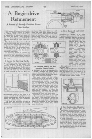
pATENT No. 387,497, by H. Katt winkel, Meissnerstrasse 28, Coswig, Saxony, Germany, describes a universal joint in which the usual forks and ring are employed,: the novel features. being, that tbo blocks (4) are made of Judd, which is described as a . material formed of fibres of asbestos iirmr•gnated with synthetic resin, known under the registered trade name of Bakelite.
These blocks are separated by others of •
rubber (21); , whigh occupy-"the spaces between them in the metal casing. Thin steel bushes (25) surround the prongs of the forks.
The right-hand view is a section on the lines A.B.
The specification does not Say Whether lubrication is needed between the forks and the bushes (25), but should it be required it is not easy to see how it can he prevented from having a damaging effect on the rubber blocks.
A Fiat Combustion Chamber.
IN patent No. 387,416 Fiat S.A. describes a form of combustion chamber for compression-ignitIon engines. This new type is described as being of a different kind to those which have recently been patented, and in which it was the main object of their designers ' to cause turbulence. In the present invention the chamber is fan shaped, with the fuel nozzle situated at the apex. In some cases both inlet and exhaust valves are situated in the chamber, but the specification also shows four valves, two in the chamber and two outside it.