


A SERVO BRAKE. ACTING IN BOTH DIRECTIONS.
Page 32
If you've noticed an error in this article please click here to report it so we can fix it.
A Résumé of Recently Published Patent Specifications,
MHE subject of servo Drakes seems to occupying the
_Lattention 01itiv:nfor's At the present moment more than any other.part of the motor vehicle'. In the present instance • the object of the inventor, Louis Renault, in specification No. 221,196, is to provide -a servo brake which will act with equal force when the vehicle is travelling in either a forward
or backward direction. .• • • The .specification points out that, in most servo brakes. the servo motors suffer from the inconvenience that they operate the brakes only when the vehicle is travelling in a forward direction, the action resembliva the winding of a cord round a rotating capstan, as used for hauling ships, etc., in docks.
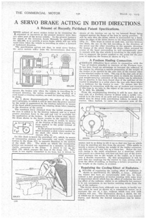
Pig. 1 shows diagrammatically the action of the usual servo principle, in which it will be seen that the power exerted by the pedal is augmented by the friction induced by means of the band which surrounds the rotating dnim when running in the direction of the arrow.
The resultant force obtained from the initial pressure ef the foot is added to by the friction induced, and so a much greater resultant force in the pull rod (A) is available for the application of the brakes. It will be evident that, should the drum shown in the figure revolve hi the opposite direc tion to the arrow, it would, by means of the friction of the band, oppose the force applied to the pedal instead of adding to it.
In the present invention a worm and wheel transmit a slow rotary motion to the shaft (B) which lies across the chassis (Fig. 2).
On this shaft is keyed the gearwheel (C), which, by means of interposing pinions and internally cut teeth, transmits motion to the drum (D) in opposite direction to the motion of the shaft (D). The studs on which the interposing pinions are mounted are supported by a member, as shown rigidly connected to the frame. A screw is cut on the shaft (D) which engages the boss of the drum (E). This drum is not rigidly connected to its boss, but is driven by
means of the friction set up by its internal flange being clamped against the flange of the boss by spring pressure. It will be seen that the drum, which is surrounded by a band, takes the place of the drum shown in the diagrammatic sketch (Fig. 1). This drum is coned on each side, and lies between two discs, the one on the left travelling in the direction of the arrow and the other travelling in the opposite direction. By Means of the sOrew thread thedrum, when arrested by means of the band surrounding, it, will automatically come in contact with the disc which is revolving in the right direction to augment the power appliedto the pedal for the purpose of applying the brakes as shown in Pig 1.
A Fordson Hauling Connection.
ERTAIN difficulties hare arisen in connection with the
use of trailers attached to tractors of the Fordson type. It has been found an advantage to increase the adhesion of the tractor by allowing a certain proportion of the weight of the trailer to be carried by the rear axle of the tractor when a two-wheeled trailer is used. The top of the rear axle of the tractor is obviously a convenient place to which the drawbar and weight-carrying extension of the trailer can be attached, but in practice it has been found that if the pull-bar of the tractor is attached to a point above the rear axle there might be a tendency for the tractor to rear. To obviate this diadvantage in connection with the Use of trailers and tractors of this type is, we take it, the object of the patent granted to W. L. Hill, No. 228,606.
From the accompanying drawing it will be seen that the rear axle of a Fordson tractor is fitted with a saddle (A), which is in the form of an arch and is provided with a slope which may be fitted with anti-friction rollers, to enable the tractor, when backed, to; raise the extension arm of the trailer, and in so doing to lift it up so that any legs on which it may be standing are free from the ground. This saddle in merely a means of taking the weight of the trailer extension, and does not act in any way as a draw-bar. Below the rear axle casing is the usual attachment for a draw-bar, which acts purely as a draw-bar, and. does not bear any of the downward pressure due to the weight of the trailer, as it forms only a flexible connection. By this arrangement it will be seen that any tendency for the tractor to rear, arising either from the effect ofi pulling, or bearing a certain proportion of the weight of the trailer, is avoided.
Regulating the Cooling Effect of Radiators. A MEANS of regulating the cooling effect of radiators is shown in specificatien No. 228,671,_A Gray. ;Although the winter has been an exceptionally mild 'one, we have noticed a fair proportion of lorries running with some kind of improvised shield which has the effect of reducing the cooling effect of the radiator, whilst in an ordinarily hot summer it is not uncommon to see lorries emitting steam front the top of the radiator.
The device shown here, although very simple, is hardly one that could be used as shown on a commercial motor, as it prevents the use of a fan, without which -very few such vehicles will run. The illustration shows a shield, the tilt of which can be regulated, by means of a link, to any desired degree, and thereby the desired temperature can 'be maintained.