


POWER LOSSES THROUGH BACK-LASH.
Page 28
Page 29
If you've noticed an error in this article please click here to report it so we can fix it.
Why it is so Important to Take Up Wear in Every Part of the Petrol Engine Including the Timing Gear.
rp HE FOLLOWING notes more par ticularly concern engines due for an overhaul after the usual mileage for a modern vehicle and they apply only to engines in which the cylinders are not offset, or in other words, to those in which the axis of each cylinder is immediately Shove that of the crankshaft.
Incidentally, as a preliminary, it may be stated that back-lash, however limited, if tested as between the two members linked together, may be very considerable if tested over an assemblage of linked parts. An instance familiar to most motorists is the play often found between the throttle and ignition levers and their respective controls.
Modern engines are mostly sent out with the timing position scored on the flywheel rim. It may be presumed, too, both that this is the dead-centre position of the piston immediately concerned and that the timing lay-out of the ignition and valves is also free from backlash.
Both conditions will be found wanting after protracted use in the case of most highspeed engines, although why this should be so as regards the dead-eentre_ position of the pistons is not so readily discernible as in the case of the timing gear, which reflects obviously the effect of wear by back-lash.
The following analysis has for its object to make both points clear and to impress on users the importance of haring verified the timing of ignition and valves after a complete overhaul, or, better still, before and after, as a means of showing to what extent any inexperience with the engine before overhaul may be debited to this sort of defect.
The "dead centre" is an old shop
term applied to the relative positions, of piston and crankpin coupled by the connecting rod at either extreme of the piston's top and bottom travel. To ascertain this only requires the use of some form of trammel-gauge with the ends pointed and bent at right angles, and using one of the ends as a fixed point from some nearby neutral or nonmoving part, e.g., a base-chamber lug. Or the frame, or a transverse stay, whilst the other is free to scribe the periphery of the flywheel.
Finding the "Dead Centre."
It is then necessary to bring one of the pistons to the point of its dead travel on the compression stroke, which is verifiable in most motors by a wire-spoke passed through a try-cock or other means of communicating the Motion of the piston to the wire. Then, with the free. end of the trammel in contact with the periphery of the flywheel, as shown in Fig. 2, the crankshaft should be slowly rocked to and fro just sufficient to cause the slightest trace of motion at the piston, the trammel point being used to seribe the extreme of the flywheel's to and-fro motion. The centre of these extremes is the dead centre, and should be centre-punched to retain it.
The degree of 'angularity of a connecting rod, of course, varies With such factors as stroke or crank-throw and connecting rod length, but even with the least pendulum motion a considerable distance will be found between the commonly accepted dead centre and the actual one as properly ascertained. In a four-cylinder unit it will be necessary to take the mean for each pair of pistons, the crank-throws being 180 degrees apart.
Before attempting synchronization or relative correctness for all cylinders, the whole range of moving parts must be free from back-lash and also the correctness of the h.t. timer relative to the h.t. distributor.
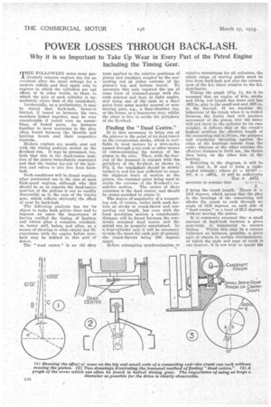
Taking the graph (Fig. 1), let it be assumed that an engine of 4-in, stroke and 10-in, rod length has worn and has .003-in, play lathe small-end and .007-in, in the big-end. If we consider the . behaviour of the crank when it is rocked between_ the limits that will produce movement of the piston (for the latter will not move in the cylinder by its own weight), it follows that at the crank's highest position the effective length of the connecting rod is 10 ins., the gudgeon and crankpins thrusting against thki sides of the bearings remote from the ends ; whereas at the other extreme the effective distance is 10.01 ins., the thrust then being on the other side of the bearing.
Referring to the diagram, it will be. seen that A, B and U form a rightangled triangle ; where A2 = 10.012 102, A .4472., It will be sufficiently
Tan 0 A472 accurate to assume that
2 being the crank length. Hence 0 12.6 degrees, which means that the play in the bearings of the connecting rod alloivs the crank to rock through an angle of 12.6 degrees, on each side of "dead centre," or a total of 25.2 degrees, without moving the piston.
It is commonly assumed tha:: a small amount of back-lash between a given gear-train is immaterial to correct timing. Whilst this may be a correct inference as between, possibly, a given pair of wheels in certain circumstances, of which the style and type of tooth is one feature, it is not wise to ignore the possibility of error set up by back-lash when it concerns a train of gear and reciprocating parts, such as valve tappets actuated by cams.
With a helical-gear timing lay-out the factor of tooth back-lash is less prominent, but is replaced by the back-lash of end-thrust. Hence a reason why it is customary, when a cross-gear drive is naecl, to place the magneto and water pump opposed to each other at the ends of the transverse shaft so that they balance the end-thrust.
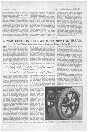
Fig. 3, which embodies a correctly plotted and measured-up instance of back-lash on timing-gear wheels, shows clearly the amount of error which can be found, even in the case of a helical-gear driven pair of timing wheels. The diagram also emphasizes the value of using as large a diameter as possible for a helical-gear timing drive.
As lateral displacement of a circular train effects a circumferential displacement of the driven member, the result can be set down in degrees of circum ference. In the lay-out cited, for the same displacement (a—b) the angle is inversely proportional to the diameter of the pinion, being only 10 degrees for a wheel....of radius R., as compared with 20 degrees for the wheel of half the radius of the larger wheel.
The diagram at the left shows the flywheel keyed to the shaft which carries the small skew-gear pinion meshing with the two-toone corresponding camshaft pinion. ..A
deviation of only 3 nun, in a timing gear, as shown in Pig. 3, will effect a difference of 4 degrees or more if the pinion be smaller than the scale lay-out depicted. A corresponding alteration of the larger, or camshaft pinion, of an equivalent size to that shown, may cause a cumulative errOr of 10 degrees (in one verified case 15 degrees) in the
i.e., relative to the dead centre of each crankpin taken in turn.
The diagram also suggests the corresponding error set up by uncorrected angular thrust in a skew-gear drive. This thrust tends to displace the shaft and skew pinion towards the right. Obviously this effect has an equivalent • influence on the relative positions of the camahaft to the crankshaft.