


Gas Turbine for Road Vehicles
Page 26
If you've noticed an error in this article please click here to report it so we can fix it.
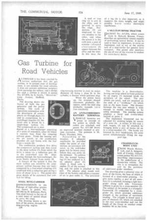
A LTHOUGH it has been asserted by Fl various authorities that the gas turbine, in its present state of development, is not suitable for road vehicles, it does not prevent ambitious inventors from pursuing the subject, and a design for such a turbine is shown in patent No. 617,856, by S. Grylls, " Marazion," Lime Avenue, Duffield,
Derby.
The drawing shows the layout of both the gas generator and the power turbine. The cycle of operations commences with the drawing-in of atmospheric air through ducts (1) and its compression by a centrifugal impeller. (2); the latter unit is driven by a single-stage turbine (3). The compressed air is next ducted to a heat-exchanger consisting of a series of concentric tubes (4) where it receives heat from the outgoing exhaust gases. From the heating unit the air travels to the combustion chamber. (5) and burns with the fuel from a nozzle (6).
The combustion products first drive the compressor turbine and then travel to the main turbine (7), from which the drive is taken via a reduction gear (8) to the road-wheel axle (9). After passing through the heat-exchanger, the gases finally exhaust from outlet 10.
A feature of the system is that the main turbine can overdrive the compressor turbine because they are interconnected by a free-wheel coupling (11) combined with a reduction gear giving a ratio of about 11 to I. The patent also gives details of an automatic fuel control for idling.
STEEL RING-CARRIER
IMPROVEMENTS in the 1 design of light-alloy pistons are shown in patent No. 607,966 by H. Schlosser, Paris. The chief feature is the use of a steel insert of special shape to carry the rings.
The drawing shows a section of the piston, through the ring-carrying region.
A38 A steel or iron ring (1) is cast in the alloy, and is grooved to carry the rings. Projections (2) are employed to key one member to the other, and when the piston is in the cold state, a pair of crescent shaped clearances (3) appear between the alloy and the steel. In this state, the ring-carrying member is oval, its major diameter (4) being a close fit in the cylinder, a feature which prevents slap: , When the piston heats up, the crescent shaped clearances gradually disappear, while the steel ring gradually expands into true circularity.
AN ANTI-CORROSION BATTERY TERMINAL
VJEHICLE batteries are V prone to corrode at the points at which the cables are attached, and patent No. 617,168 shows an improved terminal claimed to prevent corrosion. The patentee is M. Pucci, Florence, Italy.
According to the inventor, if adequate ventilation be provided under the point of connection, no corrosion will occur, as the acid-laden gases will be blown away before they can settle on the terminal. To achieve this, the normal battery lug (1) has soldered to it an adaptor plate (2) which is fitted with a replica (3) of the normal , lug, and the cable is attached to this part. The adaptor plate stands well clear of the battery and allows a current of air to pass under it. The provision of a leg (4) is also important, as it supports the extra weight, and might possibly have some electrolytic significance.
A MULTI-PURPOSE TRACTOR
PATENT No. 617,956, which comes from E. Bobard, Beaune, France, describes an agricultural tractor capable of performing several duties. It can be used to haul an implement, to carry an implement, and to act as the motive unit of a semi-trailer for general farm transport. The patent also mentions the use of two of the tractors in tandem for extra-heavy duties.
The machine is a three-wheeler, having one large wheel in front powered by an engine (1) mounted inside the periphery of the wheel. The rear wheels are small, and are mounted on the ends of a " wishbone" (2) which acts as the main frame. The distance between the two rear wheels is wide enough to enable row-crops to be safely traversed. The steering system employs a bevel and crown-wheel located at point 3.
The implement illustrated can be adjusted for working height by means of a lever (4). A trailer, in -this case a tank wagon, (5) can be attached by bringing down a pair of hooks (6) on to a cross-member (7). The hooks are lowered by their hand-levers, the same action simultaneously lifting the sup
port legs.
CHASSIS-CUMBODY UNIT
FROM Morris Motors, Ltd., and A. Issigonis, both of Cowley, Oxford, comes patent No. 617,715, describing improvements in the underframe of a chassis-less vehicle. The aim is to strengthen the
unit by the provision of additional girder members.
The drawing gives a pictorial view of most of the frame, the base of which is formed of a sheet-metal pressing.To give extra rigidity, a pair of sill members (1) is attached, forming a light-boxgirder along each side. Transverse stiffness is given by a cross-member (2). The subject of the patent is a triangular framework (3) connected by a crossgirder (4), which provides additional strength at the position of maximum loading. The triangle is based upon a pair of channels (5), which are attached to the rear cross-member and run the length of the frame to another crossmember (6) at the front.