


Patents Completed.
Page 24
If you've noticed an error in this article please click here to report it so we can fix it.
Complete specifications of the following patents will be sent to any address in the United Kingdom upon receipt of eightpence per copy at the Sales Branch, Patent Office, Holborn, W.C.
LUBRICATOR. — Lamplough and Others.—No. 13,658, dated 27th June, 1908.—This invention relates to lubricators of the type having a rotating valve which delivers oil to a number of delivery pipes. A suitable casing is provided having an inlet and an outlet and within this casing is mounted a rotating piston. On the spindle of the piston is rigidly mounted a sun pillion which gears with planet pinions mounted on
pins carried by the casing. These planet pinions gear in turn with internal teeth formed on a rotating spring-pressed distributing valve. The rotating piston farces lubricant to the rotating valve, which latter distributes the lubricant to a number of delivery pipes. In order to indicate to an observer when the lubricator is working, each delivery pipe is connected with a separate chamber which is closed on one side by a flexible diaphragm. This flexible diaphragm is in contact with a spring-loaded piston, which, when the diaphragm is moved, causes a coloured fluid to flow up a glass sight-tube.
SWITCH.—Wynne.—No. 9,156, dated 28th April, 1908.—This switch is particularly intended for use in the testing of ignition systems. It consists of a block of insulating material bored to receive the high-tension cable at one end and with a connection for coupling to a sparking plug at the other end. Midway between the high-tension cable and the
plug connectiun is a transverse hole in which two flanged members are arranged to slide, These flanged members
are connected together by means of a screw, and surrounding the joint is a metallic band. Two springs, electrically connected with the high-tension cable and the plug connection respectively, are arranged to force balls against the transverse member. When the transverse member is in one position, electrical connection is established between the high-tension cable and the plug connection by means of a metallic band, but, when the transverse member is moved into its other position, the connection is broken, owing to the interposition of the insulating material.
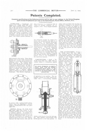
CARBURETTERS. — Paull. — No. 16,185, dated 30th July, 1908.—This invention relates to carburetters capable of operating in any position. The carburetter consists of a body portion provided with a ft.el-retaining chamber which is fed directly from the fuel supply. This chamber communicates with curved grooves in the body portion. A
rotary valve provided with very fine perforations is adapted to be moved over the grooves so that oil lodged in the grooves may he sprayed directly into the carburetter. The valve is provided with an upwardly extending flange that fits within a sleeve secured between the body portion and a cap. The sleeve has two ports formed in it, the positions of which correspond to that of the grooves, and the flange has similar ports formed therein. The valve is made integral with a spindle that passes through the body portion and is held against a machined face on the body portion by a spring, acting against a collar. The spindle is supported in ball bearings, and the valve is rotated by means of a lever, operated in the usual way. The cap, the sleeve and the body portion are held together by bolts.
EIRE EXTINGUISHER.--Zwicky.— No. 10,320, dated • 12th May, 1908.— This invention relates to portable fireextinguishing apparatus. The apparatus consists of two chambers, placed one above the other. The upper chamber contains a powder and the lower chamber compressed air. Within the upper chamber is arranged a central tube which communicates, at its lower end with the compressed air chamber, and at its upper end it supports a small cylinder which in turn accommodates a nozzle. This nozzle normally closes an opening provided in the top of the powder chamber and is attached to a piston mounted within the small cylinder. In the wails of the nozzle is a number of holes, and these communicate with the small cylinder. Surrounding the central tube are two washers which constitute a movable bottom for the powder chamber and which are adapted to be forced upwards by the air pressure.
The operation of this device is as followa:--When the needle valve in the air chamber is opened, air passes into the central tube and escapes through small holes arranged in the lower portion thereof to the under side of the afore mentioned washers, thus tending to force the powder out at the top. At the same time the air passes through the holes provided in the nozzle of the small cylinder and forces the piston therein to gether with the nozzle downwardly against the action of a spring, with the result that the opening in the top of the powder chamber is uncovered and the powder allowed to escape. The air issuing at the top of the nozzle causes the powder to be distributed in all directions.