


The Two New Tillings for Olympia.
Page 35
If you've noticed an error in this article please click here to report it so we can fix it.
The First Published Descriptions. Concluded from Las( Week (page 60b).
In our last issue we described in detail the interesting engines of the two new Tilling models ; we now proceed to deal with the transmissions.
The clutch may be dismantled when required to renew the leather without haying first to take the gearbox adrift. A neat form of fibre-faced clutch stop is fitted, and is provided with a spring take-up. This stop is adjustable without interfering with the initial compression of the spring. The gearbox is a compact and substantial unit, and, like the engine, is mounted on the sub-frame. Three speeds and reverse are provided, the direct drive on top giving 18 m.p.h. Positive interlocking of all gears is a notable feature. The shafts are kept short and run on ball bearings. All the gears are made of chromenickel steel suitably hardened and ground. The change-speed is effected by means of a pivoted hand lever working in a gated quadrant. The change-speed quadrant and the hand-brake. fulcrum bracket are each mounted on separate centres, thus eliminating erossjam when applying the hand brake.
The usual form of double universally-jointed propeller shaft is disposed between the gearbox and back axle, thus constituting a liveaxle-driven type of machine. The final drive is by means of worm and worm wheel. The worm itself is made out of chrome-nickel steel, case-hardened and ground, the wheel being cut out of hard phosphor-bronze. On both machines the worm shaft is located on top of the axle in a suitable housing. The worm whee:, along with the dif
ferential gear, is enclosed in a sturdy mild-steel casting in one piece, which also forms an outer cover for the differential shafts. A reinforcing steel tube, machined out of solid bar, is forced by hydraulic pressure into the casting at the joint, where it is bolted to the spring-seat bracket : a remarkably strong back-axle unit is the result. The differential shafts, which take the driving torque only, may each be withdrawn upon removing the rear-wheel hub caps. The braking accommodation on the machines has also received careful attention M every detail. Duplex brake drums are bolted directly to each rear road wheel ; thus, none. of the transmission gear is subjected to braking strains. The foot-brake takes effect on the inner drums by means of expanding cast-iron shoes, the hand brake by external grip of Ferodo-lined steel bands on to the outer drums. Compensating gear is fitted to each set of brakes.
We next directed our attention to the frame and springing. The pressed-steel frame, we were informed, is constructed of 45-ton tensile steel for the side members, the cross members themselves being made out of 32-ton steel_ The component appeared to be well built up. The frame sides are straight from end to end, and, upon measurement, we found the section to be 5 ins. by 178 ins. The general suspension calls for no special mention; it conforms to usual practice. We might, however, state that no torque rods are fitted on these models, the front half of the rear springs taking the drive. A straight-through transverse shaft
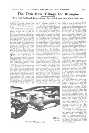
anchored at the readshackles makes a satisfactory form of tierod across that frame portion. Concerning the road wheels, this maker has again given evidence of practical experience. The wheels themselves are of cast steel ; those at the rear are provided with chrome-nickel-steel centres, accurately machined, hardened and ground within high limits. These run on phosphor-bronze floating bushes. The outer faces of the hubs are cross-milled, and accommodate dogs machined on a flange located at the outer end of each differential shaft. These flanges are bolted to the road wheels, but the bolts, as we have implied, do not take all the driving stress. This method of relieving bolts of undue stress, we would mention, is adopted throughout the chassis where occasion lends itself, as, for instance, at the forward end of the propeller shaft, the flywheel coupling, etc. The front road wheels are mounted on Timken roller bearings.
On the Bl model which we inspected the wheels were shod with K.T. tires, but we understand that Shrewsbury Challiners will be adopted as standard. The respective tire sizes are :—Front, single, 30 ins. by 3 ins., rear, twin, 32 ins. by 5i ins. The leading dimensions of the machine are :—wheelbase, 9 ft. ; track, 4 ft. 6 ins. ; over rear hubs, 5 ft. 6i ins. ; length behind dash, 9 ft. Ili ins. ; height of frame from ground when loaded, 2 ft. 4 ins. approximately.
As we have previously mentioned, the one-ton and two-ton models largely coincide, the principal feature in which the 132 type, the two-tonner, differs from the lighter machine being, of course, in the engine, which is a 20 kh.p. unit ; in this case the respective bore and stroke are 90 mm. and 120 mm. The cooling-water circulation is by means of a centrifugal pump. It has been thought well to provide for four speeds on this model, as, of course, much heavier loads will be carried. The normal top ' speed, direct driven, is 13 m.p.h. The tire sizes are increased to 30 ins. by 3i ins, on the front wheels, and on the rear by 34 ins. by 7 ins. The wheelbase is 10 ft. 6 ins., and track gauge 4 ft. 9 ins. Length behind dashboard, 11 ft. 10 ins.
In addition to exhibiting the two chassis which we have introduced to our readers, we understand that Thomas Tilling, Ltd., intends to stage two complete machines for which the bodies are well in band. It only remains for us to add that the exhibit will merit the serious attention of all prospective users who visit Olympia.