


Further Ricardo Combustion chamber Developments
Page 60
If you've noticed an error in this article please click here to report it so we can fix it.
A Résumé of Recently Published Patent Specifications That Are Obtainable From the Patent Office, Price Is. Each
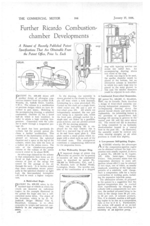
PATENT. No. 439,426 shows still . another clesign of • oil-engine coin-bustion-chamber froth ti;e prolific H.R..Ricardo, 21, Suffolk Street, London.
. The scheme is a irnadification of previous designs which we have described in past issues. Referring to the accompanying drawing, a spherical combustion chamber (1) has a lower half (2) which is heat insulated, in order to attain a high working temperature. Connection with the cylinder is made through a tangential pas
''sage . (3): So much has been previously. described, but the present patent discloses a further' niodification. This consists of the distribution of the, compressed air between the spherical chamber and a space at the top "of the cylinder, which may take the form of a hollow (4) in the piston crown. The latio or the chamber-cunt-passage volume to the volume of the piston recess is stated to be about 50-50.
An advantage claimed for the scheme is that compression heat losses are redived at high loads, owing to the absence of part of the energy loss caused by the passage. of the air through the neck. It is further stated . that since combustion occurs principally in the spherical chamber on light load, the heat-insulated hemisphere will tend to reach a higher temperatare, A Multi-wheel Bogie.
.DATENT No. 439,101 refers to the 1 'heaviest type of vehicle in which the wheels are mounted on individual ; bogies ; in the example illustrated in the • patent the bogie also has a selfcontained motor drive. The object of the invention, which is by H. W. .10nkhoff, Berger (Rhein) Ufer 4, Dusseldorf, Germany, is to effect economies .in weight and material, particularly in he suspension arrange
:. meats. • n46 In the drawing, the assembly is shownyivoted to the chassis' by a kingpin (1) from which a fork descends, terminating in a cross pivot-shaft (5). Carried on this shaft are a single frontwheel rocker arm (6) and a pair of
rear-wheel arms (3). All wheels are independently mounted, the rear pair each being on a separate arm, whilst the front pair, although carried. by .a single arm, are linked by a parallelogram of levers, and are pivoted around a pin (7) for steeling purposes.
Only one leaf-spring (4) is employed for the four wheels; this is fixed to a rearward lug of arm 6 and at its end bears upon plate 2. This plate carries a small pinion which engages with a short rack on each of the rear-wheel arms. This arrangement constitutes a compensating differential for the suspension forces.
A New Wellworthy &raper Ring.
AN improved design of piston ring intended to prevent the by-passing of excessive oil into the combustion space is described in patent No. 439,353 by Wellwortby, Ltd., and J. W. Howlett, both of Radial Works; Lytnington, Rants. The novelty consists of the• combination of a stepped
ring with tapering notches cut across one radial face. Au accompanying drawing shows two views of the ring.
If Only one ring is to be used, the smaller diameter would be placed at the bottom, but an alternative scheme is described in which two such rings may be placed in the same groove; in this case the smaller, diameters would be adjacent to each other.
A Continental Front-wheel Suspension.
I N patent No. 439,007, G. Broulhiet,
201, rue de Grcnelle, Paris, describes a design of front-wheel assembly employing independent suspension. The accompanying drawing shows the general layout clearly and needs little explanation. An interesting feature is the provision of up-and-down ball bearings (3) moving in grooves in the central post (4) and the outer sleeve (I). The central rod (2) is described as being connected to an hydraulic shock-absorber housed in a central bore in the post (4). As illustrated, the assembly would be vertical only when steering straight; at all other positions it would lean slightly.
A Low-pressure Self-igniting Engine.
ASCHEME whereby the advantages of the compression-ignition engine can be obtained without the high compression ratio usually required, is shown in patent No. 439,423 by H. Capdet, 127, All& Saint-Agne, Toulouse, France. This inventor states that the temperature necessary to cause selfignition (about 475 C.) can be attained in two ways, one of which, as usually employed, consisting of the high-compressiOn of a relatively cold charge. Such a compression calls for a heavy construction of working parts, including the expensive injection pump.
The alternative scheme, as proposed in the patent, is a• suggestion that the ignition temperature may be reached more expeditiously by charging the cylinder with a comparatively hot mixture, the method proposed being to include in the charge some 20 per cent. to 33 per cent, of exhaust products. This, it is claimed, enables a self-igniting engine to be run on a comprevion, ratio as low as 5 to 1. Furthermore, the system will permit of an air-fuel mixture being used, thus avoiding the necessity of an injection pump.