


THE SCAMMELL SIX-WHEELED TRACTOR-LORRY.
Page 12
Page 13
Page 14
If you've noticed an error in this article please click here to report it so we can fix it.
Details of an Interesting Machine Designed to Carry a Useful Load of 7 Tons 10 Cwt. Without Any Axle Weight Exceeding 6 Tons.
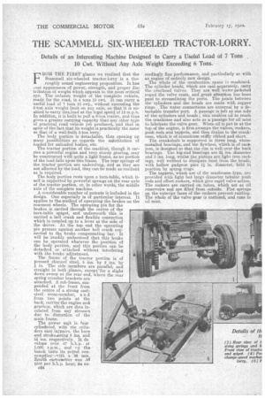
F, ROM THE FIRST glance we realized that the Scan-al:tell six-wheeled tractor-lorry is a thoroughly sound engineering proposition. It haa ,nat appearance of power, strength, and proper die-, tribution of weight which.appeals to the most critical eye. The unladen weight of the complete vehicle, ready for the road, is 4 tons 10 cwt. It Can carry a useful load of 7 tons 10 cwt., without exceeding the 6-ton axle weight limit on any axle, so that it is enabled to tarry this load at the legal speed of 12 m.p.h. In addition, it is built to. pull a 6-ton trailer, and thus gives a greater carrying capacity than any other type of practical road vehicle yet produced., and that in spite of the fact that its weight is practically the same as that of a well-built 3-ton lorry.
The, body portion is detachable, thus opening up many possibilities. as regards the substitution of loaded for unloaded bodies, etc. The tractor portion of the machine, though it carries a powerful engine and very sturdy gearing, may be constructed with quite a light frame, as no portion of the load falls upon this frame. The rear springs of the tractor portion are underslung, and as they are not affected by the load, they can be made as resilient as is required.
The body portion rests upon a turn-tabIe,. which itself is supported by powerful springs on the rear axle of the tractor portion, or, in other .words, the middle axle of the complete machine.
A considerable number of patents is included in the design. One especially is of particular interest. It applies to the-method of operating the brakes on the rearmost wheels. The operating pin for the brakes is carried through the centre of the turn-table spigot, and underneath this is carried a bell crank and flexible connection which is coupled up to a lever at the side cif the driver. At the top end the operating pin presses against another bell crank connected to the brake compensating bar.. It will be readily understood that this brake can be operated whatever the position of the body portion, and this portion can be detached or attached without interfering with the brake adjustment. • The frame of the tractor portion is of pressed channel steel, 5 ins. by 2 ins, by ii in. The side members are parallel, and straight in both planes, exceptlor a slight down sweep at the rear end, where the rear spring crossbar brackets are attached. A sub-frame, suspended at the front from the centre of a strong caststeel cross-member, a n d from two points at the back, carries-the engine and gearbox, which are thus insulated from any stresses due • to distortion of the main frame.
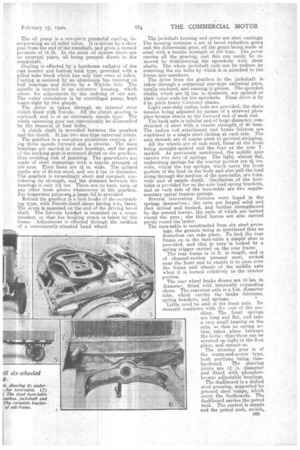
The power unit is your cylindered, with the cylinders cast int.pairs. the bore and strokeaoeing 5 ins. and 5i• ins. respectively. It de veIops over 47 b.h.p.. at 1,000 r.p.m., and • (ia the bench tests its petrol eonsumption.,vith a 36 min.. zenith carbultetter was .5fl pint. per b.b.p. hour, an ex
c24 ceedingly fine performance, and particularly so with an engine of entirely new design. The whole of the eonibustion space machined. The cylinder heads, which are cast beparately, carry the overhead valves. They are well water-jacketed rolind the valve seats, and great attention has been paid to streamlining the ports. The joints between the cylinders and the heads are made with copper rings. The water connections are external by a detachable transfer port. A passage is left at one side of the cylinders and heads ; this enables oil to reach the crankcase and also acts as a passage for oil mist to lubricate the valve gear. When oil is put in at the top of the engine, it first swamps the valves, rockers, push rods and, tappets, and then drains to the crankcase, which is of aluminium stiffly ribbed and short.
The crankshaft is supported in three long, whitemetalled bearings, and tte flywheel, which is of cars-iron, is designed so that the rim. is well over the back
bearings. The big-end bearings are ins, diameter and 3 ins, long, whilst the pistons are light iron castings, well webbed to dissipate beat from. the heads, with hollow gudgeon pins 1 in. diameter, held in position. by spring rings.
Thetappets, which are of the mushroom. type, are provided with light but large diameter tubular push rods and offset rockers, which give rapid valve action. The rockers are carried on tubes, which act as oil reservoirs and are filled from. outside. Flat springs on the exteripr faces Of the rockers prevent rattling. The whole of the valve gear is enclosed, and runs in cil mist.
The oil pump is a one-piece gunmetal casting, incorporating an oil relief valve. it is driven by a skew gear from the end of the -camshaft, and gives a normal pressure of 15 lb. In the main oil system there are .. no external •pipes, oil being pumped direct to the crankshaft: Cooling is effected bya handsome radiator of the cast header and bottom tank type, provided with a gilled tube block which has only four rows of tubes. Cooling is assisted by an aluminium fan running on ball bearings and driven by a Whittle belt. The spindle is carried in an eccentric housing, which allows for adjustment by the undoing of one nut. The water circulation is by centrifugal pump, kept water-tight by two glands.
The drive is taken through an internalcone clutch lined with Ferodo. All the eluteh gearing is enclosed, and is of an extremely simple type. The whole operating gear can conveniently be dismantled by the removal of four bolts.
A clutch shaft is provided between the -gearbox and the clutch.. It has two star-type universal joints.
The gearbox is. a one-piece aluminium casting, giving three speeds forward and a reverse. The main bearings are carried in steel housings, and the gate cf the striking gear is mounted direct .on the gearbox, thus avoiding risk of jamming. The gearwheels are made of steel stampings with a tensile strength of 100 tons. Their faces are lf in. wide. The splined shafts are of 60-ton steel, and are 2 ins. in diameter. The gearbox is exceedingly short and compact, considering. its strength, and the distance between the bearings is only 10j ins. There are no keys, nuts, or any other loose pieces whatsoever in the gearbox. For inspection purposes..a large lid is provided. Behind the gearbox is a foot brake of the contracting type, with Ferodo-lined shoes having 5-in, faces. The drum is mounted on the end of the driving bevel shaft. • The fulcrum bracket is mounted on a crossmember, so that the braking strain is taken by the frame. Adjustment is effected through the medium of a conveniently-situated hand wheel.
The jackshaft housing and cover are steel castings. The housing contains a set of bevel reduction gears and the differential gear, all the gears being made of steel with a tensile strength of 100 tons. The cover carries all the gearing, and this can easily be removed by ewithdrawing the sprockets with their shafts. The whole jackshaft unit can be undone by removing the six bolts by which it is attached to the
frame sicte members. • The drive from the gearbox to the jackshaft is taken through a compound star-type universal joint, totally enclosed, and running in grease. The sprocket shafts, which are 2 ins, in diameter, are splined at their cuter ends for the sprockets. Final drive is by 2-in, pitch heavy Coventry chains.
Light cast-steel radius rods are provided, the chain tension being adjusted by means of -a screwed phosphor-bronze sleeve at the forward end of each rod.
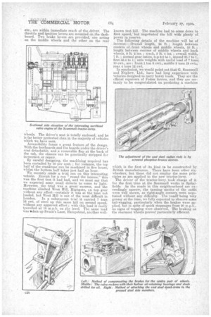
The back axle is tubular and of large diameter, eonstructed of steel with a tensile strength of 60 tons. The radius rod attachment and brake fulcrum are combined in a single steel casting at each side. Tim axle threads are of coarse pitch to prevent stripping. All the wheels are of cast steel, those at the front being straight-spoked and the four at the rear Yspoked. As previously mentioned, the middle axle carries two sets of springs. The light, almost fiat, underslung springs for the tractor portion are 2i ins. wide, whilst the top springs, which carry the front portion of the load on the body arid also pull the load along through the mediuin of the turn-table, are 3-ins. wide and of ample depth. Oscillation of the turntable is provided for on the axle load spring brackets, and at each side of the turn-table are two supplementary spiral tension springs. Several interesting features were found in the springs themselves; the eyes are forged solid and then drilled and bushed, and further strengthened by the second leaves, the ends of which are turned round thefl eyes ; the third leaves are also carried partly round the latter.
The turn-table is constructed from six steel pressings, the gussets being so interlaced that no distortion can take place. To lock the rear frame on to the turn-table a simple shoe is provided, and this in turn is locked by a spring trigger carried on the rear frame. The rear frame is 14 ft. in length, and is
of channel-section pressed steel, arched near the front end to enable it to pass over the frame and wheels of the middle axle when it is turned relatively to the tractor portion.
The rear wheel brake drums are 16 ins, in
diameter, fitted with internally expanding shoes. The rearmost axle is a 3-in, diameter tube, which carries the brake fulcrums, spring brackets, and springs. • Little need be said of the front axle. Its strength conforms with the Lest of the machine. The front springs are long and flat, and take a very small bearing on the axle, so that no spring actione takes place between the bolts ; thus these can he screwed up tight in the first place, and remain so. The steering gear is of the worm-and-sector type, 'both portions being casehardened. The steering joints are l .7.n. diameter and fitted with phosphorbronze adjustable bearings. The dashboard is a dished steel pressing, supported by pressed steel ramps, which carry, the footboards. The dashboard carries the petrol tank. The control is simple and the petrol cock, switch, etc., are within immediate reach of the driver. The throttle and ignition levers are mounted on the dashboard. Two brake levers are provided, one acting on the middle wheels and the other on the rear wheels. The driver's seat is totally enclosed, and he is far better protected than in the majority of vehicles which we have seen.
Accessibility forrns a great feature of the design. With the footboards and the boards under the driver's scat detachable, and a removable flap at the back of the cab, the chassis can be practically Stripped fcr inspection or -repair. By careful designing, the ma.thining required has been curtailed by 50 per cent. ; for instance, the top half of the crankcase can be machined in five hours, whilst the bottom half takes just half an hour. We recently .made a trial run on this interesting vehicle. Except for a run "round the houses," this was the first test it had had, and we must say that we expected some small dereets to come to light. However, the trial was a great success, and the machine climbed West. Hill, Highgate, cn top gear without any .effort—certainly it was at the time not loaded', but West Hill is one of the most difficult in
London. In a subsequent trial it cosrieci 7 tons 16 cwt. of steel up this same hill on second speed, without any apparent effort ; with this load it easily travelled -Ett 18 mph. on the level. The same load was *ken up Swain's Lane, Hampstead, ancther well known test hill. The machine had to come down to first speed, ' but negotiatedthe hill with plenty of power in reserve.
The following details of the machine will be of interest:—Overall length, 24 ft. ; length between centres of front wheels and middle wheels, .10 ft. ; length between centres of middle wheels and back wheels, 9 ft. 2 ins. ; track, 5 ft. 4 ins. ; overall width, 7 ft. ; normal gear ratios, tcp 9.6 to 1, second 23.7 to 1, , first 46.4 to 1 axle weights with useful load of 7 tons; 10 cwt., are : front 1 ton 9 cwt., middle 5 tons 19owt.., rear 4 toils 12 cwt.
In conclusion, we would point out that G. Scammell and Nepliesir,' Ltd., have had long experience with vehicles designed to carry heavy loads. They are the cfficial repairers of Foden lorries, and they are certainly to be Congratulated On 'producing a machine
which is the first of its kind to be constructed by British manufa.cturers. There have been other sixwheelers, but these did not employ the same principles as are applied to the new tractor-lorry.
The driver of the tractor-lorry, took charge of it for the firSt, time at the Seammell works in Spitalfields. As the roads in this neighbourhood. are exeeeedingly narrow, the turning merits of the outfit were well shown, as right-angle corners were negotiated without any difficulty. The i'oad. i' being very greasy at the time, we fully expected to Observe some. tail-wagging, particularly when the brakes were applied, but in spite of quick stoppages from 20 in.p.he no signs of wagging were observed. The braking on the rearmost wheels proved particularly efficient,