


Patents Completed.
Page 20
If you've noticed an error in this article please click here to report it so we can fix it.
Humber Spring Axle-Torque Members. Improved Magneto Bearings. A Clutch for Light Vans. Shock-reducing Gear-change.
Copies of complete specifications of the patents published on this pare can be obtained from the Sales Patent Office, Holborn, W.C., at the cost of sixpence for each specification.
R. B. NORTH and A. M. ALLEN, No. 130, dated 4th January, 1915.—This invention relates to improvements in the construction of bearings for magneto generators, and is illustrated as applied to the mounting of the distributor shaft. A casing for the bearing is made in two parts screwed together. The outer or left-hand part has a fairly thick flange, by which it is secured to the framing of the magneto, and the whole casing projects into the space between the magnets. The ends of the casing are closed by flanges wnieli eVeend in wardl-y and closely surround the spindle. A ball bearing is mounted at each end of the casing to receive the spindle, and a spacing-sleeve maintains them apart in their correct position. The easing is filled with grease or other lubricant. It will be seen that with this construction the whole bearing must be removed with the spindle, and it cannot be dismantled until so removed. The working parts on the spindle, however, are all accessible' as the driving gear is mounted on the free end outside the bearing, and the distributor contacts are mounted on a disc of ebonite secured on the end of the sp:ndle.
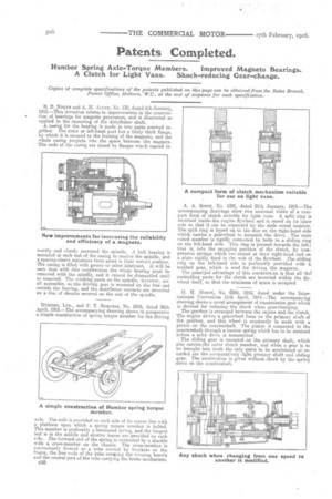
HUMBER, LTD., and F. T. BURGESS, No. 5916, dated 20th April, 1915.—The accompanying drawing shows in perspective a simple construction of spring torque member for the driving axle. The axle is provided on each side of its centre line with a platform upon which a spring torque member is bolted. This member is preferably a laminated spring, and the longest leaf is in the middle and shorter leaves are provided on each s:de. The forward end of the spring is connected by a shackle with a cross-member on the chassis. The cross-member is conveniently formed as a tube carried by brackets on the frame, the free ends of the tube caraying the running boards and the central part of the tube carrying the brake mechanism.
e60
A. A. SCOTT, No. 1291, dated 26th January, 1915.—The accompanying drawings show two sectional views of a compact form of clutch suitable for light vans. A split ring is mounted inside, the engine flywheel and is coned on its inner side so that it can be expanded by the male coned member. The split ring is keyed on to the disc on the right-hand. side which carries a ge-arwheel to transmit the drive. The male coned member is rigidly connected by bolts to a sliding ring on the left-hand side. This ring is pressed towards the left; that is, into the engaging position of the clutch, by compression springs which are seated at the;r right-hand end on a plate rigidly fixed to the web of the flywheel. The sliding ring on the left-hand side is preferably provided with a toothed gear, which is used for driving the magneto.
The principal advantage of this construct:on is that all thel controlling parts for the clutch are mounted within the flywheel itself, so that the minimum of space is occupied.
G. H. MoaaN, No. 6995, 1915, dated under the International Convention 11th April, 1914.—The accompanying drawing shows a novel arrangement of transmission gear which is devised for reducing the shock when gear-changing. The gearbox is arranged between the engine and the clutch. The engine drives a gearwheel loose on the primary shaft of the gearbox, and this wheel is constantly m mesh with a pinion on the countershaft. The pinion is connected to the countershaft through a torsion spring which has to be strained before a solid drive is transmitted. The sliding gear is mounted on the primary shaft, which also carries.,the outer clutch member, and when a gear is to be brought into mesh the only parts to be accelerated or retarded are the comparatively light primary shaft and sliding gear. The acceleration is given without shock by the spring drive on the countershaft.