


A Novel Dutch Agricultural Implement
Page 56
If you've noticed an error in this article please click here to report it so we can fix it.
A Résumé of Recently Published Patent Specifications
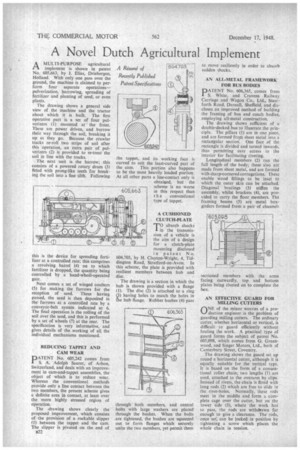
AMULTI-PURPOSE agricultural implement is shown in patent No. 605,663, by J. Elias, Driebergen, Holland. With only one pass over the ground, the machine is claimed to perform four separate operations— pulverization, harrowing, spreading of fertilizer and planting of seed, or even plants.
The drawing shows a general side view of the machine and the tractor about which it is built. The first operative part is a set of four pulverizers (I) mounted at ' the front. These are power driven, and burrow their way through the soil, breaking it up as they go. Because the crawler tracks re-roll two strips of soil after this operation, an extra pair of pulverizers (2) is provided to re-treat the soil in line with the tracks.
The next unit is the harrow; this consists of a powered rotary drum (3) fitted with prong-like teeth for breaking the soil into a fine tilth. Following this is the device for spreading fertilizer at a controlled rate; this comprises a revolving barrel (4) on to which fertilizer is dropped, the quantity being controlled by a hand-wheel-operated gate.
Next comes a set of winged coulters (5) for making the furrows for the reception of seed. These having passed, the seed is then deposited in the furrows at a controlled rate by a conveyor-belt system indicated at 6. The final operation is the rolling of the soil over the seed, and this is performed by a set of wheels (7) at the rear. The specification is very informative, and gives details of the working of all the individual mechanisms mentioned.
REDUCING TAPPET AND CAM WEAR
PATENT No. 605,242 comes from S. A. Adolph Saurer, of Arbon, Switzerland, and deals with an improvement in cam-and-tappet assemblies, the object of which is to reduce wear. Whereas the conventional methods provide only a line contact between the two members, the present scheme gives a definite area in contact, at least over the more highly stressed region of operation.
The drawing shows clearly the proposed improvement, which consists of the provision of a rockable slipper (1) between the tappet and the cam. The slipper is pivoted on the end of B22 the tappet, and its working face is curved to suit the least-curved part of the cam. This portion also happens to be the most heavily loaded portion. At all other parts a line-contact only is obtaitted, but the scheme is no worse in this respect than t h e conventional type of tappet.
A CUSHIONED CLUTCH-PLATE TO absorb shocks in the transmission of a vehicle is the aim of a design for a clutch-plate mounting disclosed in• patent No. 604,703, by H. Clayton-Wright, 4, Tiddington Road, Stratford-on-Avon. In this scheme, the plate is provided with resilient members between hub and disc.
The drawing is a section in which the hub is shown provided with a flange (1). The disc (2) is attached to a ring (3) having holes to match the holes in ale hub flange. Rubber bushes (4) pass through both members, and central bolts with large washers are placed through the bushes. When the bolts are tightened, the bushes are squeezed out to form flanges which securely unite the two members, yet permit them to move resiliently in order to absorb sudden shocks.
AN ALL-METAL FRAMEWORK FOR BUS BODIES PATENT No. 606,365, comes from S. White, and Cravens Railway Carriage and Wagon Co., Ltd., Staniforth Road, Darnall, Sheffield, and discloses an improved method of building the framing of bus and coach bodies, employing all-metal construction.
The drawing shows sufficient of a double-decked bus' to illustrate the principle. The pillars (1) are in one piece, and are formed from sheet metal into a rectangular section'. One face of the rectangle is divided and turned inwards, thus permitting easy access to the interior for facilitating riveting.
Longitudinal members (2) run the full length • of the body; these also are made from sheet metal, and are formed with sharp-cornered corrugations. These enable wood fillings to be inset to which the outer skin can be attached. Diagonal bradings (3) stiffen the assembly, whilst brackets (4), are provided to carry the floor members. The framing beams (5) are metal boxgirders formed from a pair of channel-t sectioned members with the arms facing outwardly, top and bottom plates being riveted on 'to complete the box.
AN EFFECTIVE GUARD FOR MILLING CUTTERS OFNE of the minor worries of a production engineer is the problem of guarding milling cutters. The ordinary cutter, whether horizontal or vertical, is difficult to guard efficiently without fouling the work. A practical type of guard forms the subject of patent No. 605,098, which comes from G. Greenwood, and Singer Motors, Ltd., both of Canterbury Street, Coventry.
The drawing shows the guard set up round a horizontal cutter, although it is equally suitable for the vertical type. It is based on the form of a conuntional roller chain; two lengths (1) are used, attached to the overarm by Clips. Instead of rivets, the chain is fitted with long rods (2) which are free to slide in the rivet-holes. Normally, these rods meet in the middle and form a complete cage over the cutter, but on the lower side (3), where the work has to pass, the rods are withdrawn far enough to give a clearance. The rods, once see, can be locked in position by tightening a screw which places the whole chain in tension.