


Dual• Steering for Agricultural Tractors
Page 36
If you've noticed an error in this article please click here to report it so we can fix it.
A Resume of Patent Specifications that Have Recently
Been Published
ACCORDING to th e Ford 'Motor Co., Ltd., 68, Regent Street, Lon
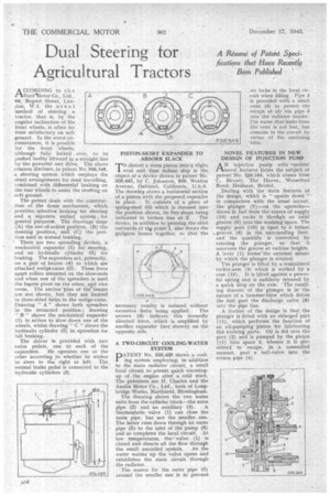
W./, the us u a 1 method of steering a tractor, that is, by the angular inclination of the front wheels, is often far from satisfactory on soft ground. In the worst circumstances, it is possible for the front Wheels, although fully locked over, to be pushed bodily feirward in a. straight line by the powerful rear drive, The above concern discloses, in patent No. 556,348, a steering system _which employs the utual arrangements for road travelling, combined with differential braking on the rear wheels to assist the steeting on soft ground.
The patent deals with the construction of the drum mechanism, which provides selective braking for steering and a separate unified. system . for general purposes. The drawings-'sliow (A) the out-of-action position, (B) the steering position, and (C) the position used in normal braking.
There are two spreading devices, a mechanical expander (1) fat' steering,. and an hydraulic cylinder (3) for braking. The expanders act, primarily, on a pair of beams (4) to which are attached wedge-cams (2). These force apart rollers mounted on the shoe-ends and when one of the spreaders is used the be,arns pivot on the other, and vice versa. The anchor pins of thebeams are not shown, hut they are located in three-sided holes in the wedge-cams. Drawing " A" shows both spreaders in the retracted position; drawing " B " shows the mechanical expander (1) in action to slow down one of the wheels, whilst drawing " C " shows the hydraulic cylinder (3) in.operation'ior lull braking.
The driver is provided with two extra pedals, one to each of the expanders.. Ile operates one or the other according to whether he wishes to steer to the right or left. The normal brake pedal is connected to the hydraulic cylinders (3). PISTON-SKIRT EXPANDER TO ABSORB SLACK
rdistort a worn piston into a slight val and thus reduce slap is the -object of a device shown in patent No 55,8,443, by C. Johnston, 509, Weldon Avenue, Oakland, California, U.S.A. The drawing shows a horizontal section of a piston with the proposed expander
in place. It consists of a piece of spring-steel (3) which is stressed into the position shown, its free shape being
indicated in broken line at 2. The device, in addition to pressing the skirt outwards A thie point 1, also draws the gudgeon bosses together, so that the
necessary ovality is induced without excessive force being applied. The arrows (4) indicate this inwardly directed force, which is amplified by another expander (not shown) on the opposite side.
A TWO-CIRCUIT COOLING-WATER SYSTEM PATENT No. 556,459 shows a cooling system 'employing, in addition to the main radiator circuit, a Small local circuit to permit quick warmingup of the engine after a cold start. The patentees are H. Charles and the Austin Motor CO., Ltd., both of Longbridge Works, Northfield, Birmingham.
The drawing shows the two water exits from the cylinder block—th6 main
pipe (2) and an auxiliary (3). A thermostatic valve (1) can close the main pipe, but not the smaller one. The latter runs down through an outer pipe (5), to the inlet of the pump(6) and so completes the local circuit. At low temperatures, the valve (1) is closed and directs all the flow through
the small uncooled system. As ,the water warms up the valve opens and establishes the main circuit through the radiator.
The reason for the outer pipe (5) around the smaller one is to prevent air locks in the local circuit when filling. Pipe 3 is provided with a small vent (4) to permit the escape of air via pipe into the radiator -header: The water that leaks from the vent is not lost, but remains in thp circuit by virtue of the enclosing tube,
. NOVEL FEATURES IN NEW DESIGN. Or INJECTION PUMP AN injection pump with '.several novel features forms the subject of patent No. 5,,53,164, which comes from C. Nevatt, . The 'Haven, Waterford Road; Henleaze, Bristol.
,Dealing with the main features of the 'design, which is " upside down "-in comparison with the usual layout, .the plunger (7)on the upstrokedzaws'in fuel from the source of supply
(10) and sucks it .throtigla an axial groove (9) into'the working space. The supply port (10) isopen to a helical. groove. (6) in the surrounding liner. and thequantity is controlled by rotating the plunger, so that it uncovers the groove.at various heights. A lever (1) forms' the external means by which the plunger is rotated, The plunger is lifted by a trunnioned rocker-arm (3) which is worked by a cam (12). It is lifted against a powerful spring and is suddenly released by a quick drop on the cam. The resulting descent of the' plunger is in the nature of a hammer-blow which drives the fuel past the discharge yalVe. (8) into the pipe line.
A feature of the design is that the plunger is fitted with an enlarged part (11), which performs the function of an oil-pumping piston for lubricating the\ working parts. Oil is fed into the Port (2) and is pumped by the piston (11) into space 5, whence it. is permitted to escape, in. a controlled manner, past a ball-valve into the return pipe (4).