


keeping them running
Page 56
Page 57
If you've noticed an error in this article please click here to report it so we can fix it.
by Trevor Longcroft
Shortcuts on brake repairs may not only be bad practice from a safety point of view; the result is usually the development of an early brake fault which brings the vehicle back into the work shop for even longer fault diagnosis and rectification.
It's a point worth mentioning next time your traffic department is pushing for a vehicle — and you don't have to take my word for it. When I visited the Girling service centre in Birmingham, I learned that many cases of premature lining wear and even brake failure which are brought to their attention could have been avoided if the job had been correctly done in the first instance..
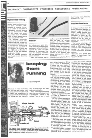
Examples of what can crop up with the 2LS hydraulic wedgeoperated brake is over stroking or running the tappet rollers off the wedge flank, And uneven lining wear caused by incorrect Setting of the bellcrank pushrodlever system. This wear takes the form of a tapering of lining thickness toward one end of the lining arc or tapering across the section of the lining.
To see the significance of this it is best to understand how the brake works.
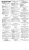
The 2LS is a two-leading-shoe unit, each shoe operated by a bellcrank/pushrod system actuated by the hydraulically withdrawn wedge. The unit offers twin-leading-shoe braking in forward and reverse and is normally fitted to rear axles. A single-leading-shoe version, the 2LS1, is commonly fitted to front axles and as the designation implies offers the twin-leadingshoe facility in one direction only —forward.
The brake shoes are moved outward to the drum by a tappet and roller assembly which bears on the wedge. As the wedge is withdrawn the rollers "move up" the inclined face.
The system uses a transverse operating cylinder mounted perpendicular to the back plate and parallel to the axle line. As fluid is pushed into the cylinder, the cylinder sleeve which is connected to the wedge drawlink moves and withdraws the wedge. A further lazy link projecting from the rear of the sleeve is linked to, and permits actuation of the mechanically applied handbrake through the hydraulic cylinder. The correct positioning of the sleeve relative to the wedge drawlink and hand-brake connector is critical, if over-stroking is to be avoided and efficien1 braking achieved.
Expansion of the shoes is dependent upon the length 01 stroke of the wedge and thut it is critical to maintain the ful length of stroke during setting Any mistake could leave the tappet roller anywhere along the wedge, when the brakes are released. Upon brake applicatior only a limited amount of trave is left, braking efficiency is im paired or lost or overstrokinc occurs.
When fitting replacemen shoes the bellcrank and push lever system must be properh reset — a simple procedure provided one follows the manual If anything, the pushrod shouli be a fraction tight when revolvint it with the finger tips.
When setting any type c wedge brake is is fundaments to the operation that the wedg is fully retracted and stays secur ed in this position throughou setting. To do this the brak adjuster is wound on until th drum locks; once locked in thi way it is unlikely that the brak will be incorrectly set. The handbrake linkage and iperating cylinder should also le disconnected.
Once the drum is locked the ctuating cylinder can be bolted D the backplate and the cylinder leeve slid into position and crewed on to the wedge drawnk.
Locking the wedge means that me sleeve can be correctly ositioned without fear of withrawing the wedge and thus !tering the effective wedge troke. There are various types I transverse cylinder and the tter should consult the manual ir the correct sleeve clearances I his particular one. With the -ekes still locked in position id the park-brake lever disenaged the hand-brake linkage in be connected to the lazy mk on the cylinder. Again, lockg the drum means that the ikage can be set without risk limiting the wedge stroke. irther it is important to ensure e engagement of ample threads take the hand-brake load. mould this not be done, handake failure could result.
Undue slack in the hand-brake kage should be taken up by own adjusting assembly. mder no circumstances should a cylinder hand-brake linkage altered for this purpose.
When adjustments and setting ve been completed, the drum! oe clearance should be set cording to the manual. Follow] the procedure and using the mai, the complete stroke of m wedge is employed for brake plication and trouble in service Juld be avoided.