


A Pump for Chassis Lubrication
Page 66
If you've noticed an error in this article please click here to report it so we can fix it.
PATENT No. 751,102 deals with multiple-point lubricating pumps and comes from Auto Research Corp.-, 129 South State Street, Dover, Delaware, U.S.A.' The device described runs at a slow speed for normal lubrication but is also fitted with means for manual operation. This is to enable a shot of
oil to bc given before starting the vehicle after it has been standing for a long period.
In operation, the pump piston (1) is slowly raised by the arm (2) as the latter is lifted by a cam (3). The cam is driven from the shaft (4) by a primary worm-drive followed by several pairs of spur reduction gears.
The piston compresses a spring as it rises, and when the cam-roller runs over the rapid slope (5) the piston descends rapidly to discharge a quantity of lubricant.
To enable the piston to be manually operated, the cam is provided with a pin-and-slot connection to its driving gear, lightly loaded by a torsion spring. If the piston is forced down by external means, the cam offers no obstruction, because it can turn due to the pin-andslot coupling.
AN IMPROVED REAR-VIEW MIRROR
DAZZLE from behind via the rear view
mirror can be annoying, and in such circumstances drivers often tip the mirror into a non-operative position. The correct working position is then difficult to find again. To help in this respect is the purpose of a mirror fitting shown in patent No. 750,848 (Tudor Accessories, Ltd., Beaconsfield Road, Hayes, Middlesex).
The mirror (1) is arranged to pivot about its thick 'upper edge, being held upwards by a spring (2). The lower edge can be moved horizontally, to either the dipped position (as shown) or by a spring catch (3) to the front corner R32
,(4) at which angle it reflects normally.
In operation, the driver, having put the mirror out of action, has only to flick it back into place without any need for careful re-setting. The initial setting is permitted by ball joint 5.
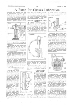
TOOL FOR COMPRESSING VALVE SPRINGS
AUSEFUL maintenance tool is shown in patent No. 756,562 (J. Wilderspin, College Farm, Fen Dray ton, Cambridgeshire) It is for ccmpressing valve springs and is arranged so that the user can have both hands free for manipulating the cotters.
The drawing makes the scheme quite clear; a fork-end (1) engages the spring collar while the necessary compressing force is supplied by ,a cylinder and piston (2) direct on to the valvehead.
Hydraulic fluid is used to move the piston. It is supplied via a flexible pipe from a foot-operated pump, not shown.
A SID&LIFTING FORK TRUCK L'ORK-TRUCKS work ing in narrow gangways often have difficulty in picking up loads lying at the sides, and parent No. 750,793 (ElectraHydraulics, Ltd., Liverpool Road, Warrington, Lanes), discloses a design of truck more suitable for this purpose.
The proposed vehicle is fitted with a cross-slide (I) at the front upon which the main lifting carriage can be moved sideways. Hydraulic or electric motive power is used for this purpose sand .a means is adopted to prevent the carriage from slewing out of the vertical. This consists of a pair of raeks (2 and 3) which is engaged by ty‘ pinions mounted on a common vertic shaft behind member 4.
The drawing shows a vehicle havin only a one-sided pair of forks; i another scheme the fork-carrying men ber is mounted on a king-pin so ON it can be swung to either side.. Powt is also applied for this movement.
NEW TYPE SHOCK ABSORBER
riA HYDRAULIC shock-absorber .pei milling free ..movement in on direction but imposing a restriction i the other, is shown in patent N( 750,522 by N. Butcher and others, .6 Fortess Road, London, N.W3. Tb novel point is that the restriction to .th fluid flow is made in the form of a pa of porous material.
The drawing shows a dual construe tion intended for damping the oscil lations of a torsion-rod (1). When th, rod is turned it depresses one or othe of a pair of pistons (2). The fluil under the piston is trapped and cai escape only by flowing through th. porous pad (3) at a limited rate.
On the upstroke, the cup (4) holdin; the pad acts as a one-way valve and by lifting frofn its seat, enables ai unobstructed return flow to OMIT.
AIRCRAFT RE-FUELLING
ATANK wagon adapted to be use for re-fuelling aircraft is describe( in patent No. 752,730 (Thompsot Brothers (Bilston), Ltd., Biyston, Staffs) From the tank, a flexible delivery 'hos( supported by a jib or boom, can bi swung into the best position for filling