


Rubber Mounting for Propeller-shaft Bearing
Page 42
If you've noticed an error in this article please click here to report it so we can fix it.
A Rdszund of Patent Specifications that Have Recently Been Published
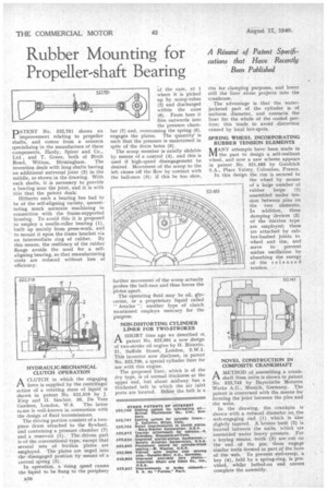
PATENT No. 522,751 shows an improvement relating to propeller shafts, and comes from a concern specializing in the manufacture of these components, Hardy, Spicer and Co., Ltd, and T. Green, both of Birch Road, Witton, Birmingham. The invention deals with long shafts having an additional universal joint (2) in the middle, as shown in the drawing. With such shafts, it is necessary to provide a bearing near the joint, and it is with this that the patent deals.
Hitherto such a bearing has had to be of the self-aligning variety, necessitating much accurate machining in connection with the frame-supported housing. To avoid this it is proposed to employ a needle-roller bearing (1), built up mainly from press-work, and to mount it upon the frame bracket via an intermediate ring of rubber, By this means, the resiliency of the rubber flange avoids the need for a selfaligning bearing, so that manufacturing costs are reduced without loss oi efficiency, HYDRAULIC-MECHANICAL CLUTCH OPERATION
ACLUTCH in which the engaging force is supplied by the centrifugal action of a rotating mass of liquid is shown in patent No. 522,519 by J. I-Cep and H. Sinclair. 38, De Vere
Gardens, London, W.S. The latter 'turtle is well-known in connection with the design of fluid transmissions.
The driving portion consists of a twopiece drum attached to the flywheel, and containing a pressure chamber (7) and a reservoir (I ). The driven part is of the conventional type, except that several sets of friction plates are employed. The plates are urged into the disengaged position by means of a central spring (5).
In operation, a• rising speed causes the liquid to be flung to the periphery
of the case, at 1 where it is picked up by scoop-tubes (2) and discharged within the cone (6). From here it flies outwards into the pressure chamber (7) and, overcoming the spring (5), engages the plates. The quantity' is such that the pressure is maintained in spite of the drain holes (8).
The scoop member is axially slidable by means of a control (4), and this is used if high-speed disengagement be desired. Movement of the scoop to the left closes off the flow by contact with the ball-race (3); if this be too slow, further movement of the scoop actually pushes the ball-race and thus forces the plates apart.
The operating fluid may be oil, glycerine, or a proprietary liquid called " Aroclor "; another type of clutch mentioned employs mercury for the purpose.
NON-DISTORTING CYLINDER LINER FOR TWO-STROKES
CAA SIIORT time ago we described in patent No. 522,001 a new design of two-stroke oil engine by H. Ricardo, 21, Suffolk Street, London, S.W.1. This inventor now discloses, in patent No. 522,730, a special cylinder liner for use with this engine.
The proposed liner, which is of the dry type, is of normal thickness at the upper end, but about midway has a thickened belt in which the air inlet ports are located. Below the belt is a rim for clamping purposes, and lower still the liner alone projects into the crankcase.
The advantage is that the waterjacketed part of the cylinder is of uniform diameter, and contacts the liner for the whole of the cooled portion; this tends to avoid distortion caused by local hot-spots.
SPRING WHEEL INCORPORATING RUBBER TENSION ELEMENTS 1% ANY attempts have been made in IVI the past to design a self-resilient wheel, and now a new scheme appears in patent No. 521,483 by Goodrich S.A., Place Valmy, Colomhes, France.
In this design the rim is secured to the wheel by means of a large number of 521.483 rubber loops (1) assembled under tension between pins on the two elements. In addition, three damping devices (2) of the friction type are employed; these are attached by rubber-bushed joints to wheel and rim, and serve to prevent undue oscillation by absorbing the energy of the released tension.
NOVEL CONSTRUCTION IN COMPOSITE CRANKSHAFT
CAA METHOD of assembling a crankshaft from units is shown in patent No. 522,745 by Bayerische Motoren Werke A.G., Munich, Germany. The patent is concerned with the means for forming the joint between the pins and the webs.
In the drawing, the crankpin is shown with a reduced diameter on the web-engaging end (1) which is also slightly tapered. A bronze bush (2) is located between the units, which are assembled under heavy pressure. For a keying means, teeth (3) are cut on the end of the pin; these engage similar teeth formed in part of the bore of the web. To prevent end-creep, a key (4), held by a spring-ring, is provided, whilst bolted-on end covers complete the assembly.