


HINTS ON MAINTENANCE.
Page 26
If you've noticed an error in this article please click here to report it so we can fix it.
How to Get the Best out of a Vehicle, to Secure Reliability and to Avoid Trouble.
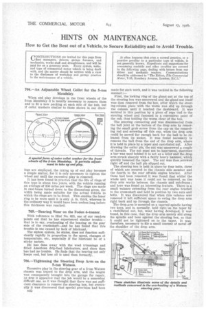
704.—An Adjustable Wheel Collet for the 5-ton Maudslay.
When end play develops in the front wheels of the 5-ton Maudslay it is usually necessary to remove them and to fit a new packing at each side Of the hub, but If collet washers similar to those shown in our draw ings are employed, the taking up of end play becomes a simple matter, for it is only necessary to tighten the wheel nut until the excessive play is removed.
It has been found in practice that the life of rings of this type is about two years, with the vehicle running an average of 350 miles per week. The rings are made in cast-brass turned down to the dimensions given, the width being made suitable for the actual vehicle to which the rings are to be fitted. This enables the inner ring to be worn until it is only in. thick, whereas in the ordinary way it would have been useless long before this thickness was reached.
705.—Bearing Wear on the Foden 6-tonner.
With reference to Hint No. 695, one of our readers points out that he has experienced similar trouble-that is to say, overheating of the bearing on the gear side of the crankshaft—and he has found that this trouble is one caused by lack of lubricant.
The siphon system, he states, does not function sufficiently rapidly in proportion to the speed, changes of temperature, etc., especially if the lubricant be of a sticky nature.
Ile has done away with the wool trimmings and fitted American drip-feed lubricators, and since then has had no trouble. He finds that the bearing not only keeps cool, but less oil is used than formerly.
706.—Tightening the Steering Drop Arm on the 5-ton Watson.
Excessive play in the steering gear of a 5-ton Watson chassis was traced to the drop arm, and the wagon was consequently brought into the garage for repair. At first it appeared that the job would be a somewhat difficult one, as it was thought that there was not sufficient clearance to remove the steering box, but eventually it was discovered that special provision had been e42 made for such work, and it was tackled in the following manner :— First, the locking ring of the gland nut at the top of the steering box was unscrewed and the gland nut itself was then removed from the box, after which the steering-column plate with the worm was slid up through the column until it touched the dashboard. It was secured in this position by a piece of rope tied to the steering wheel and fastened to a convenient point of the cab, thus holding the worm clear of the box.
The steering connecting rod was disconnected from the ball joint at the bottom of the drop arm by removing the small grub screw from the cap on the connecting rod and screwing off this cap, when the drop arm could be moved far enough back for the ball to be released from its socket. It was found necessary to remove the ball from the end of the drop arm, where it is held in place by a taper and castellated nut. After drawing the cotter pin, the nut was unscrewed a couple of threads. The nut must not be hanvaered, therefore a bar was used behind it to act as a lever and the drop arm struck sharply with a fairly heavy hammer, which quickly loosened the taper. The nut was then ,screwed right off and the ball pin slipped out.
The steering box is held in place by four bolts, three of which are secured to the chassis side member and the fourth to the rear off-side engine bracket. After these had been removed it was found that whilst the whole unit was loose it could not be removed, as the drop arm works between the chassis and sub-frame; and here was found an interesting feature. There is a small valance extending from the rear engine bracket to the cross-shaft and held in position by two nuts and bolts. It was discovered that when this valance was removed it left sufficient space to swing the drop arm right back and up through the chassis.
The drop.-arm is mounted on a tapered spindle having two keys, and is, normally, held tight on the taper by a castellated nut, but, wear having developed, it was found, in this ease, that the drop arm merely slid along the spindle and bore against the steering box, so that it could not be tightened on to the taper. It was, therefore, necessary to file a small amount of metal off the shoulder of the drop arm.