


THE. BUS -BODY AND ITS MOUNTING.
Page 23
Page 24
Page 25
If you've noticed an error in this article please click here to report it so we can fix it.
The Need for Harmony Between Body and Chassis and Certain Ways in Which it is Secured.
THE •ideal motor vehicle may be defined as one wherein there is complete harmony between body and chassis. In order to achieve this end it has been realized that there must be close co-operation between the engineer and body-builder. The special passenger chassis, the low frame, better suspension, and the more shapely radiator and bonnet are familiar instanees of a better understanding of the bodybuilder's requirements.
One of the obstacles which stand in the way of perfection is that the bus body is often. twice the width of the chassis, so that adequate support must be provided for this side overhang. The method of mounting should also make some allowance for the unequal flexing of the chassis which takes place when the vehicle is being driven over uneven road surfaces.
The Coachbuilder's Blue Print.
The first step towards successful mounting consists of designing the body to fit the chassis accurately. When making the working drawing, the body-builder is guided by the coachbuilder's print supplied hy the motor manufacturer. The body-builder has no difficulty in ascertaining the body space of the chassis, the location of the steering wheel and the position of the hind axle, but occasionally he is in doubt as to the height of the chassis and the clearances necessary round the wheelarch. The motor manufacturer should state definitely the height of the chassis under certain body weights and again when fully loaded, quoting the figure on which the weight of passengers is calculated. By this means the height of the steps can be set out with contidenee.;.. The height of the chassis when the empty body is on It is useful for reckoning the height of the steps, since the bus will not be always full, whilst the height of the chassis when under full load is of value for calculating the minimum clearance under the bottom slat of the lifeguard. The behaviour of the chassis under full load is of -particular importance also for determining the hind-wheel clearances. The body-builder wants to make the wheel-arch as small as possible, because any increase in height tends to interfere with seating comfort.
Therefore, the motor manufacturer should not stipulate any measurement in excess of practical requirements, and give close attention to the question of the inter-relation of wheel diameter, spring deflection and the height of the frame, with a view to reducing this measurement whenever the conditions allow. But this is no easy matter, since the frame is several Inches lower than formerly. Maybe there is too much conservatism regarding wheel diameter and the amount of vertical movement required in the system of springing, wIlich has to play its part in giving comfort, whether the bus be fully Wen or otherwise or the road good or bad.
Rigidity of the Frame.
The modern chassis frame is often arched over the hind axle, or it may have a cranked tail end or be curved down sharply behind the dash. The frame must not be weakened by any special profile adopted, but, on the other hand, be rigid enough to retain its shape and be proof against fracture.
The weakest part of a chassis is often immediately behind the dash, especially with a front-entrance bus,. and, therefore, any cranking o? the side members here should be well reinforced. The tail end has to support considerable weight at times in a back-entrance bus, the amount of stress depending on the amount of overhang beyond the hind axle. Excessive overhang is not favoured nowadays, and the 7-24ths of the overall length, as suggested by the Ministry of Transport, is
generally followed, although, outside the Metropolitan area, not necessarily enforced. The .arching of the chassis frame over the hind axle, although it tends to decrease its rigidity and must be compensated for by the use of a deeper section, has to withstand little direct stress, especially in a single-decker, as the body is more or less built round it.
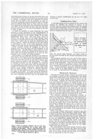
The Bottom Frame of the Body.
In order to make the best use of a low chassis, the body-builder does his utmost to keep the floor level as close to it as the construction allows. The difference in height of the floor and the chassis is represented by the thickness of the bottom framework required. The most important members of this bottom framework are the cross-bars or bearers which run the full width of the bottom of the body.
The simplest way of giving strength to a cross-bar is to make it thick, rather than wide. But thickness is just the element which the designer of a low floor wishes to suppress. Therefore, the solution lies in strengthening the comparatively thin bottom frame by means of suitable steel plating laid edgewise or by inserting thee plates instead of bolting them on outside or by the use of channel or T-iron.
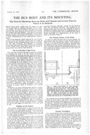
Chassis Outriggers.
If a comparatively thick cross-bar be used, it will be strong enough to sfipport the side overhang of the body, but if its dimensions have been reduced to the minimum, then strong brackets or outriggers are required, these being bolted to the web of the chassis. These mounting brackets should form a feature of every modern passenger chassis, be designed as part of it, and not left as an item to be added by the coachbuilder.
Here is another matter which calls for the co-operation of body-builder and engineer, for If the position of these outriggers is to be standardized, then due conB39 sideration must be given to the fact that both front and rear-entrance buses will be mounted on the same model of chassis. A bracket must not, therefore, be placed where there is likely to be an entrance, or, may be, alternative positions could be drilled so that a bracket could be shifted from back to front, and vice versa. The requirements of the near side would not be identical with those of the off side, so that only the near-side brackets would have to be moved according to the type of body in hand.
It might be possible, in some instances, for these brackets to form extensions of the cross-members of the chassis, giving the opportunity for setting mit corresponding members of the bottom frame of the body immediately above them. But such scope would be limited, the bottom bars of the body usually being arranged to coincide with the feet of the side pillars, in order that a plate may be used for reinforcing these bottom corners. Again, the position of the side pillars is determined by one of the more important overall lengths of the body and the equal division of that space.
These brackets should be designed so that the diagonal strut does not reach the full extension of the horizontal arm. By this means a piece could be cut off when required, should the bottom of the body be narrower than the accepted standard, or in case any nonpassenger type of body was being mounted.
The brackets, it is suggested, should not be bolted on dead square, but fitted so that the outer ends stand up from in. to -4 in„ allowing for any subsequent settling down when the full load is on and also to ensure that proper contact is made at the outer edges. A sysiera of outrigger brackets not only simplifies the mounting of a wide body, but it does away with the necessity for a substantial bottom side—that is, the outer longitudinal member of the bottom framework. These, then, need only be strong enough to form an effective distancepiece for the side pillars and act as a foundation for the edges of the floor. If a skirt panel be employed, another longitudinal is used below the bottom side position, thus stiffening the lower part of the pillars and
forming a further justification for the use of a light bottom side.
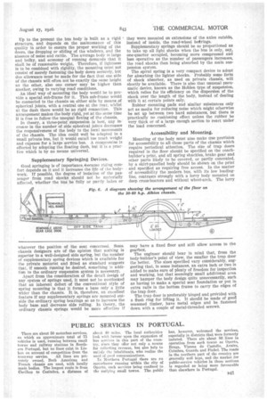
Holding-down Clips.
A bus body should never be bolted on the chassis, but clipped on. Drilling the chassis is always to be avoided; the use of bolts also weakens both the chassis and the body framework where the holes are drilled. Single bolts are also liable to shear, especially as they must be comparatively far apart. If the holding-down bolts are placed close together, too much stress is thrown upon the body by the unequal movements of the chassis.
The accepted method is by the use of clips with a coupling piece under the bottom flange of the chassis. The top of the clip bears on a metal stirrup, a piece of leather being interposed. Clips facilitate dismounting, and, if it be desired to substitute another body, there is no occasion for anxiety as to the registering of bolt holes. As each clip has to embrace a cross-bar and the chassis, which is at right angles to it, It is arranged at an angle of approximately 45 degrees.
Wheel-arch Clearance.
The rise of the hind wheel, owing to the deflection of the springs, is given on the coachbuilder's blue print either as a radius some 4 ins, greater than that of the wheel, or as so many inches vertically above the top of the frame. Usually, the clearance required between • tyre and wheel-arch has to be added to this. It is advisable always to examine the actual chassis, so as to find out what vertical movement is possible before the hind axle casing will touch the frame. The allowance decided upon may be in excess of this, but not more than 2f ins, extra is necessary to allow room for accretions of mud and small stones. Moreover, too close a fit of the wheel in the arch tends to increase local air pressure and the accumulation of mud.
The clearance required is necessarily vertical, or nearly so, even after allowing for the small radial movement of the hind axle. This being so, the allowance at the sides may be reduced to 3 ins.-4 ins., leaving sufficient space for giving access to the wheel. The space between the inside face of the wheel and the wheelarch panel is seldom less than 2 ins., to allow for side rolling. This motion is inevitable, not only when the vehicle is negotiating corners and bends in the road, but also when running on the camber of the road and passing over pot-holes.
With a low chassis, brake-drum clearance has also to be provided for, and occasionaly a dome-shaped plate is fitted to the floor above the differential casing. The arched member over the back axle of a low chassis has also to be accommodated above the general floor level, so that the• longitudinal seating will often fulfil the three functions of concealing the wheel, brake-drum arches, and the upward curved portion of the frame. The frame at this part is packed with wood, and forms a foundation to which the heel board of the longitudinal seat can be screwed.
The coachbuilder's blue print should, therefore, give not only the distance between the inside faces of the twin hind wheels, but also the diameter and distance apart of the brake drums and the shape of the frame arch, as expressed in arcs of circles.
Up to the present the bus body is built as a rigid structure, and depends on the maintenance of this quality in order to ensure the proper working of the doors, the dropping or sliding of the windows, and the absence of noise and rattle. The average body is large and bulky, and economy of running demands that it shall be of reasonable weight. Therefore, if lightness is to be combined with rigidity, the mounting must not consist of merely fastening the body down securely, but due allowance must be made for the fact that one side of the chassis will often not be exactly the same height as the other, also one corner may be higher than another, owing to varying road conditions.
An ideal way of mounting the body would be to provide a special sub-frame for it. This sub-frame would be connected to the chassis on either side by means_of spherical joints, with a central one at the rear, whilst at the dash there would be no rigid connection. This arrangement makes the body rigid, yet at the same time it is free to follow the unequal flexing of the chassis.
In theory, a three-point suspension is best, any increase in the number of side spherical joints decreases the responsiveness of the body to the local movements of the chassis. The idea could well be adapted to a small private bus, but it would entail too much weight and expense for a large service bus. A compromise is effected by adopting the floating dash, but it is a practice which is by no means universal.
Supplementary Springing Devices.
Good springing is of importance.Oecause riding comfort depends on it and it increases the life of the bodywork. If possible, the degree of isolation of the passenger from road shocks should not be materially affected, whether the bus be fully or partly laden or
whatever the position of the seat concerned. Some chassis designers are of the opinion that nothing is superior to a well-designed side spring, but the number of supplementary spring devices which is available for the private motorist and fitted as standard suggests that, if smooth running be desired, something in addition to the ordinary suspension system is necessary.
Apart from the consideration of the detail design of any system of springs used, it must not be overlooked that an inherent defect of the conventional style of spring mounting is that it forms a base only' a little wider than the chassis. It is, therefore, an excellent feature if any supplementary springs are mounted outside the ordinary spring bearings so as to increase the body base and decrease side rolling. In theory, the ordinary chassis springs would be more effective if k they were mounted on extensions of the axles outside, instead of inside, the road-wheel bearings.
Supplementary springs should be so proportioned as to take up all light shocks when the bus is only, say, one-quarter occupied, becoming more compressed and less operative as the number of passengers increases, the road shocks then being absorbed by the main suspension system.
The spiral spring is a very compact device to adopt for absorbing the lighter shocks. Probably some form of shock absorber, as used on private chassis, will shortly be available. There is also that unusual pneumatic device, known as the Holden type of suspension, which relies for its efficiency on the dispersion of the shock over the length of the body, instead of dealing with it at certain points only.
Rubber mounting pads and similar substances only act as media for reducing noise which might otherwise be set up between two hard substances, but there is practically no cushioning effect unless the rubber be very thick or of a large enough section to react under the load concerned.
Accessibility and Mounting.
Mounting of the body must also make due provision for accessibility to all those parts of the chassis which require periodical attention. The size of trap doors required in the floor should be specified on the coachbuilder's print, and all spring shackles, brake gear and other parts likely to be covered, or partly concealed, by a skirt-panelled body should be shown on the print and specified as requiring free access. In the matter of accessibility the modern bus, with its low loadingline, contrasts strongly with a lorry body mounted on deep cross-bearers and without wheel-arch. The lorry may have a fixed floor and still allow access to the gearbox.
The engineer should bear in mind that, from the body-builder's point of view, the smaller the trap door the better. The sizes specified vary considerably, suggesting that, in some instances, an extra inch or two is added to make sure of plenty of freedom for inspection and working, but that seemingly small additional area may hamper the body design quite unnecessarily, such as having to make a special seat foundation or put in extra rails in the bottom frame to carry the edges of the trap door. The trap door is preferably hinged and prOvided with a flush ring for lifting it. It should be made of good seasoned timber, have metal edges and be fastened down with a couple of metal-threaded screws.