


Patents Completed.
Page 20
If you've noticed an error in this article please click here to report it so we can fix it.
Roller-bearing
Construction. An Improved Universal Joint. Modified Magneto Design. Non-skid Devices.
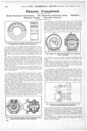
A. M. LAYCOCK, No. 100,553, dated 18th December, 1915.— In a roller bearing according to this invention, one of the race rings is provided with a central radial flange ; in the construction illustrated, this flange is formel on the inner ring, and the outer ring has two inwardly directed flanges one at each side. Two sets of rollers are arranged 134tween the rings, and they are separated by the central flange on the inner ring.
In order to avoid any tendency for the rollers to tilt, a loose ring is ,provided in alignment With the central flange and in contact with the inner ends of the rollers. This ring has oppositely projecting arms which serve as separators for the, various rollers in each set. In the operation of the bearing, the loose ring is carried round with the rollers, but it serves at all times to •transmit end-thrust from one series of rollers to the other. .
The main object of the invention is to produce a roller bearing of simple construction suitable for use in ordiikary commercial-vehicle service, which isalso comparatively inexpen. sive to manufacture.
R. PENTONY, No. 16,436, dated 22nd November, 1915.— In this joint the driving shaft is formed with a flange on which a cylindrical casing is secured. This casing carries two pins projecting inwards to engage the arms of a fork on the driven shaft to transmit. the drive to it. The joint is also adapted to take end-thrusts, by providing a spherical surface on the interior Of the outer cylinder and co-operating surfaces on the driven shaft.
In the construction illustrated the outer spherical surfaces are provided on suitable fillibg pieces inserted into the cylinder, while the inner spherical surfaces are provided by hollow shells. The whole joint is oiltight, and may be run in oil which is inserted through a suitable plug on one side. It will be seen that this joint is very convenient for assembling and erecting. If it is uncoupled from the flange on the driving shaft and the nut on the end of the driven shaft is removed, the whole joint can be slid endways relatively to the driven shaft if the forked member is splincd on that shaft.
• M. PEnnnsEri, No. 9054, dated 21st June, 1915.—This specification describes an improved construction of magnet)" in which rotating magnets are used. The base or main frame of the machine carries a cup-shaped housing which is normally stationary but can be rotated to effect the timing of the spark. A spindle extends through this housing and carries a second cup-shaped member in which the magnets are mounted. The magnets are circular in farm, but one end is bent back
upon itself so as to .be concentrie with the remainder of the magnet and to bring the poles diametrically opposite one another.
The primary and secondary windings are provided on a Ushaped armature and may be divided into sections if desired. The make-and-break is mounted on the end of the spindle outside the main frame. Details of the construction. of this part are given, in the specification.
A. H. PERKINS, NO. 10,613, dated 21st July, 1915.—The accompanying drawings show a plan and elevation of sandboitea and operating mechanism for them on a motor vehicle. A box or hopper is fitted over each wheel; it is provided, with suitable chutes to direct sand on to the ground in front of the wheel. The sand is controlled by a sliding valve at the bottom of each hopper, the two valves being simultaneously operated by a single hand-lever or pedal.
The stseaial feature of the invention is that a resilient connection is used. between the controlling lever and the valves.
In the form illustrated a bow-shaped spring rests against, two stops, and its free ends are connected to the valves. The controlling lever pulls the spring forward, and its engagement with the stops forces its ends inwards. As soon as the control lever is released the valves are automatically dosed. Insteadof the bow-shaped spring, spring-controlled tie-rods may be used.
A feature of the invention is that the device is capable of ready manipulation, whilst it can be adapted for use on existing vehicle designs.