


Patents Completed.
Page 20
If you've noticed an error in this article please click here to report it so we can fix it.
Complete specifications of the following patents will be sent to any address in the United Hingdom upon receipt of eightpence per copy at the Sale Branch, Patent Office, Holborn, W.C.
DETACHABLE RIM.—D'Hespel.-No. 5,607/11, dated under International Convention 7th March, 1910.—The invention described in this specification relates to a vehicle wheel having a de tachable rim. The wheel is formed of two dished discs, having flanges which engage and carry the rim. In order to attach the discs to the axle, each is provided with a mushroom-shaped boss; these engage with each other when the discs are in place ; a screw cap completes the fastening. In order to get at the valve, an opening is provided in one of the discs, and is covered with an elastic cover.
LUBRICATING MECHANISM.— Lancia.—No. 7,316, dated 23rd March, 1911.—This invention relates to the employment of a pair of the toothed wheels of the distributing gear or of any other Imitable part of the engine as an oil pump. In the illustration, the small pinion is secured to the crankshaft of t he engine, and, together with the large pinion, is enclosed in an airtight chamber. The oil is drawn up through the conduit shown on the right-hand side of the illustration, and is forced out through the hole shown on the left-hand side of the same figure, whence it passes to the parts to be lubricated.
IGNITION APPARATUS. — Smith and Muirhead and Co., Ltd.—No. 18,794, dated 9th August, 1910.—This specification describes apparatus that is primarily intended for use with internal-combustion engines for producing the ignition spark. It is particularly designed for starting the engine automatically, i.e., without the use of the starting
handle. According to the invention, the battery is connected up and the make-and-break device • actuated for starting by a single movement of a switch arm. A coil and switch are provided. and so arranged that, by a simple movement of the switch arm from its " off " or neutral position into one of its extreme positions, the battery circuit is made and broken through the coil by means of an auxiliary contact breaker, so that a spark or sparks is or are produced in the cylinder, the charge therein being thus fired and the engine started. During the same movement of the switch arm, the auxiliary contact breaker is cut off, and the battery-ignition circuit is closed. The battery ignition can then be cut out and the magneto ignition thrown in by moving the switch arm to its other ex
treme position. The drawings show the coil contained within a case furnished with a flange and a cover, these parts being made preferably of an insulating material. The spindle of the switch mechanism extends through the cover, and at its inner end carries a conducting sector holding an insulating bloat. This block is provided with a gap into which the free end of a spring blade of the auxiliary contact breaker may enter. This movement into the gap of the spring blade closes platinum points on the contact breaker, while the block on either side of the gap is so shaped as to open the said platinum points. Suitable electrical connections are arranged so that, when the parts are not running, the battery contact breaker, a contact spring, and the platinum points of the auxiliary contact breaker are all open, while the primary of the magneto ie earthed. In order to bring the apparatus into action and to start the engine, the switch arm is moved into the correct position, during which movement contact is first made at the platinum points and then broken, owing to the gapped edge of the insulat
ing block. This contact, however, is sufficient to commence the engine running, sparking in the cylinder then continues by means of the battery-ignition circuit. When the engine has gathered speed, the high-tension terminal on the magneto is joined up to the distributors.
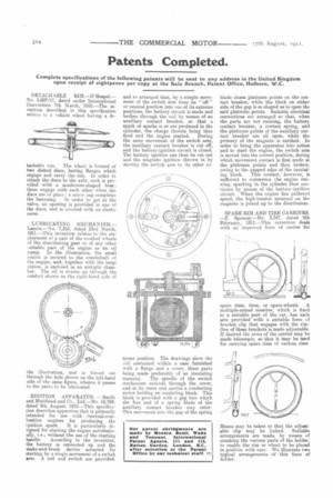
SPARE RIM AND TIRE CARRIERS. —F. Spencer.—No. 3,347, dated 9th February, 1911.—This invention deals with an improved form of carrier for spare rims, tires, or spare-wheels. A multiple-armed member, which is fixed to a suitable part of the car, has each arm provided with a suitable form of bracket clip that engages with the rim. One of these brackets is made adjustable. If desired the arms of the carrier may be made telescopic, so that it may be used for carrying spare rims of various sizes.
Means may be taken so that the adjustable clip may be locked. Suitable arrangements are made, by means of cranking the various parts of the holder, to enable the rim or wheel to be placed in position with ease. We illustrate two typical arrangements of this form of holder.