


Abridgments of Interesting Patent Specifications.
Page 16
If you've noticed an error in this article please click here to report it so we can fix it.
Eckstein and De Dion Patent Similar Ignition Devices.
No. 26,527, dated December 6th, 1904. —Electric ignition.—Eckstein and Coates, of Peel Works, Salford.—A unidirectional current, either of a uniform or variable character, may he derived from a magneto generator or dynamo (a), or from a primary or secondary battery, and whether uniform or intermittent is fed into a condenser (c) of suitable capacity, the latter being arranged to be discharged suddenly through the primary winding (d) of an induction coil or transformer (e) by means of a timing contact maker or distributor (f), which is operated by the engine in any suitable manner so as to determine the periods of ignition at the sparking-plug (g). Whilst the discharging circuit is open the condenser (c) is being charged by the generator so long as it Is at work, thereby storing sufficient energy to obtain a good ignition spark at the plug (g) when the die. charging circuit is closed. The closing of the latter by the timing contact causes a sudden rush of current from the condenser (c) through the primary winding (d) of the induction coil (e), the said winding being of comparatively low resistance and inductance, as will be well understood. This action gives rise in the secondary winding (h) of the induction coil to an instantaneous current of high voltage, which bridges the gap (i) of the ignition sparking-plug (g), or the like device, and so fires the charge in the cylinder.
No. 8,919, dated (under Convention) February loth, 1905.—Electric ignition.— De Dion and Bouton.—The source of current (x) may be a primary or secondary battery, or a magneto-electric machine,
one of the poles being connected to the mass (M) of the motor. The other end of the primary circuit (2) of the induction coil is connected to a terminal (3) on the interrupter (4). The secondary circuit (5) of the coil is connected at one end to the ignition plug (6), and at the other end to the mass (M) of the motor. At (7) is arranged a condenser, the object of which is the well-known one of decreasing the spark, which occurs when the primary current is interrupted, and increases the strength of the direct induced current. Experience has shown that an increase of the capacity of this condenser does not result in a proportionate decrease of the spark when the primary current is interrupted, and that the said condenser affects the sparks only within narrow limits. It is found that if there be arranged near the interrupter (4) an additional condenser (8), connected, on the one hand, to the primary circuit, and, on the other hand, to the mass (M) of the motor, the spark occurring when the primary circuit is interrupted is much weaker. Experiments have shown that the position of this condenser is of importance and that its effect on the spark is more pronounced the nearer the condenser is to the interrupter, and, for this reason, the condenser (8) is, as shown, arranged in parallel with the terminal of the interrupter (3).
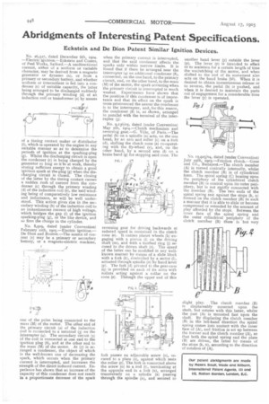
No. 9,136/05, dated (under Convention) May 5th, 1904.—Clutch mechanism and reversing gear.—G. Ville, of Paris.—The pedal (b) on a spindle (a) acts, on the one hand, by an arm and roller (c) on a fork (d), shifting the clutch cone (e) co-operating with the fly-wheel (v), and, on the other hand, by a second anti (f) on a brake band (g) for stopping said cone. The
reversing gear for driving backwards at reduced speed is contained in the clutch cone (e). It carries planet wheels (h) engaging with a pinion (i) on the driving shaft (m), and with a toothed ring (j) secured to the driven shaft (r). The speed of the latter can be modified in any wellknown manner by means of a slide block with a fork (k), controlled by a sector (1), actuated through spindle (n) by hand lever (p). The fork (d) pivoted to the gear-case (g) is provided On each of its arms with rollers acting against a collar on the cone (e). Through the upper end of this fork passes an adjustable screw (o), secured to a plate (s), against which rests the roller (c). The fork is connected above the screw (o) to a rod (t), terminating at the opposite end in a link (u), arranged transversely on a spindle (x) passing through the spindle (n), and secured to another hand lever (y) outside the lever (p). The lever (y) is intended to effect or to maintain for a certain length of time the unclutehing of the motor, and when shifted to the end of its movement also acts on the band brake (131). When it is desired to obtain instantaneous release or to reverse, the pedal (b) is pushed, and when it is desired to maintain the parts out of engagement for a considerable time the lever (y) is operated.
No. 15,925/04, dated (under Convention) July 25th, 1901—Friction clutch.—Ganz and Co., Budapest.—The clutch member
(A) is turned conically internally, whilst the clutch member (B) is of cylindrical form. The spiral spring (C) bearing upon the periphery of the cylindrical clutch member (B) is conical upon its outer periphery, but is not rigidly connected with the member (B). The two ends of the spiral spring rest against the stops (k, n) formed on the clutch member (B) in such a manlier that it is able to slide or become compressed or extended by the amount of play afforded by the stops. Between the inner face of the spiral spring and the outer cylindrical periphery of the clutch member (B) there is but very slight play. The clutch member (B) is displaceably mounted upon the shaft, but rotates with this latter, whilst the part (A) is mounted fast upon the shaft. By displacing the clutch member
(B) in the left-hand direction the spiral spring comes into contact with the inner face of (A), and friction is set up between the former and the clutch member (A), so that both the spiral spring and the plate (B) are driven, the latter by means of the stops (k, n), according to the direction of rotation of (A),