


DESIGN FOR FORK-LIFT TRACTIVE UNIT
Page 56
If you've noticed an error in this article please click here to report it so we can fix it.
THREE years after starting work on the project, Mr. C. E. Page, on engineer who has been connected with transport all his working life, has been granted a full patent on a design which promises to have applications in many branches of goods transport. The patent, which applies not only in the U.K. but also in the U.S.A., most of Western Europe and the major Commonwealth countries, is for the combination of forklift mechanical handling with road tractors or tractive units. Both' the adaptation of existing tractive units and the eventual design and construction of a new dual-purpose fork-lift tractive unit are envisaged by the patentee.
Mr. Page, who is at present commercial vehicle sales manager with a Rootes dealer in Kent, has had much interest shown in the idea by manufacturers and operators, but has not yet finalized any agreement for the manufacturing rights. As well as offering prospects of much quicker turn-round for artics working into places where mechanical handling is not readily and immediately available, the design could well. be applied to a combined shunter/fork-lift outfit in -large depots, such as at paper mills and indtistrial centres.
With the growing use of both artics, even in •medium-sized and small fleets, and palletization, Mr. Page foresees particularly economic application of his patent in this field. A loaded artic would arrive at its delivery point, the tractive unit would be uncoupled and the driver would then use its fork-lift capabilities to unload the semi-trailer. And because
• of: its size, weight and layout, a tractive unit should be able to work as a handling unit on ground too uneven for most forklift § to operate safely.
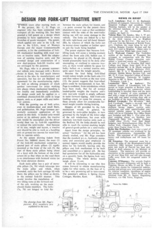
As the patent drawing (taken from .Patent No. 940844) shows, the mast (1) of the fork-lift mechanism compr;ses a spaced pair of static pillars (2) rigidly mounted at the front of the cab (3), the tops of these static pillars being about on a level with the bottom of the windscreen (4) so that when on the road there is no interference with forward vision (as the front elevation shows).
Each static pillar has a pair of moveable pillars (5a, 5b) which telescope into the static pillar and which, when extended, carry the fork carriage (6) with them; the pillars can be tilted as shown, in the normal fork-lift manner. This would involve the installation of two tilting rams at the forward end of the cab, working on the main chassis frame members. The forks (7a, 7b) are hinged to fold fiat between the static pillars for transit, and —a point covered by the patent—have elastomeric tips or caps so that accidental contact with the sides of the semi-trailer during use will not cause damage to the vehicle. The forks are linked by a bar (8) with right-hand and left-hand threads (8b), by rotation of which the forks can be moved closer together or farther apart • to suit the loads being handled.
The patent explains that because forklifting loads will cause a turning moment about the front axle (10), ballast can, if necessary, be placed at (9), though this would presumably have to be done after uncoupling, or confined to separate tractors, as there would seldom be space for bulky ballast on a normal tractive unit, quite apart from the weight penalty.
Because the -load being fork-lifted would reduce weight on the back axle (11) and thus reduce traction at the rear tyres (12), the patent suggests that four-wheel 4,drive could be incerporated; in fact, Mr. Page is confident, from calculations which have been made, that for all normal loaded-pallet weights the tractive unit's own rear-axle weight is amply sufficient to resist forward tipping. And front-axle loadings create no cause for concern, as these already allow for considerable forward weight transfer during braking.
Heights of lift provided by the fork mechanism would, in general, be governed by static-pillar heights, in turn governed by the height of the lower edge of the cab windscreen; but even with relatively low-built tractive Links such as the Bedford TK the forks should be well able to reach the normal stacking height of general-goods pallets on a semi-trailer.
Apart from the design principles, the actual " hardware " for the job has been closely studied, and Mr. Page considers that the standard p.t„-o., hydraulic pump, rams and associated gear employed on normal tippers would readily provide the drive for his fork-lift leaving only the pillars and fork mechanism to be built and assembled as a special job. He has had quotations for all the hydraulics and, on a quantity basis, the figures look very promising. The whole device would weigh about 21 cwt.
It will be interesting to see who first comes forward to obtain manufacturing rights for what seems, on the face of it, to be a very promising aid to turn-round. The patentee's address is Spring Grove Cottages, Marden, Kent, H.B.C.