


NEW ONE-MA] 40 FT. BU
Page 42
Page 43
Page 44
If you've noticed an error in this article please click here to report it so we can fix it.
AN all-hydraulic one-man-operated bus for 48 seated and 32 standing passengers is to be exhibited at the Amsterdam Commercial Motor Show by A.B. Scania Vabis, Sodertalje, Sweden. [t is 40 ft. long and has an eight-cylinder in-line engine mounted transversely at the rear, driving through a torque converter to a single-reduction bevel gear in the rear axle. The windscreen wipers, door gear, radiator shutters and brake, steering and throttle controls are all operated hydraulically.
The new Scania Vabis bus, termed the Metropol, has been developed in conjunction with the Mack Manufacturing Corporation of America for use in Stockholm and, after extended trials of a prototype in Sweden, Stockholm Tramways have ordered 200 of this type. Scania Vabis have now acquired the sole manufacturing rights for Europe and may export the Metropol to all countries apart from America.
Shortage of operating staff and high wages have been largely responsible for the development of the bus-, which is equipped with a powerful engine and simplified driving controls, thus enabling one man to operate the vehicle with the minimum waste of time. During the trials it was established that with one-man operation, a
" 12 m.p.h. schedule could be run, making 10 sec. stops every quarter of a mile and keeping to a maximum speed of about 25 m.p.h.
The bus is 8 ft. wide and weighs 9 tons 16 cwt. unladen, which, after making an allowance of 154 lb. for each of the 80 passengers, represents an all-up gross running weight of 15 tons 8 cwt., of which 9 tons 14 cwt. is carried on the reac axle. Where heavier axle loads are permitted the Metropol can be arranged to accommodate 130 passengers. In this case, a conductor would be carried. Except for those over the wheel-arches,
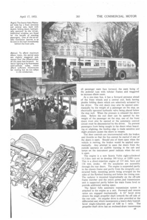
all passenger seats face forward, the seats being of the pedestal type with tubular frames and staggered to increase elbow room.
As a one-man bus, it has a forward entrance ahead
of the front wheels and a central exit, both having clouble folding doors which are selectively actuated by the driver. The exit doors may also be opened automatically by the weight of a passenger on the step, an electrically operated hydraulic valve being placed below the step well. When the pressure is released the doors close. Before the exit door can be opened by the weight of the passenger on the step, one of the front doors must also be opened or the automatic control circuit must be disconnected by the driver. To prevent passengers from being caught in the doors when boarding or alighting, the leading edge is made sensitive and slight pressure causes the doors to reopen.
The door controls are interconnected with the brakes and throttle so that the bus cannot be started if one of the doors is open. Should one of them open when the vehicle is moving, the brakes would be applied automatically. Any attempt to open the doors from the outside operates an audible warning in the cab and lamps on the instrument panel indicate when the exit is open.
The engine is a new Scania Vabis eight-cylindered 11.3-litre unit set to develop 180 b.b.p. at 2,000 r.p.m. This is a direct-injection engine of 115 mm. bore and 136 mm. stroke. All the auxiliaries are accessible through the rear doors. The engine is suspended partly in the chassis frame and partly from the integrally constructed body, mounting points being arranged on the sides of the flywheel housing and below the timing case. The radiator is mounted longitudinally on the off-side frame member and the entire power_ and transmission unit is supported partly below the main frame level to provide additional seating space,
The Spicer fully automatic transmission system is attached to the engine as a unit. Forward and reverse ratios are engaged mechanically. A sr bevel drive directs the single propeller shaft towards the off side of the rear axle. An angular drive is also provided at the differential end, which incorporates a heavy-duty hypoidbevel single-reduction gear of 4.88 to 1 ratio. The propeller-shaft drive has an enclosed-drum transmission
brake of 12-in, internal diameter, in which a 5-in, shoe is operated by the hand brake. It is claimed that this brake will hold the fully laden bus on a 15 per cent. gradient.
An engine-driven pump supplying a pressure-bag accumulator mounted on the rear overhang provides hydraulic power for the controls. Additional hydraulic equipment includes a reservoir, pressure regulator, reducing and operating valves and special interlocking valves for the door, brake and throttle gear. External operating cylinders are provided for the front and rear brakes. The large cast-iron drums have cooling fins, reinforcement ribs and dampers to prevent squeal. All the drums are of 161 in, internal diameter,,A 5 in. wide shoe is used at the front, with similar shoes in pairs at the rear.
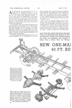
The steering column is a two-piece jointed unit with the base and first section bolted vertically to the frame and the upper part set to an angle of 271°, thus enabling the driving position to be located nearer the front. A bevel drive replaces the conventional drop arm, and steering-wheel movement is transmitted in a rotary
motion through a universally jointed shaft to a Bendix hydraulic servo unit mounted directly on the axle beam. There is mechanical linkage through this unit to the drag link as a safeguard against failure of the hydraulic system. The drag link is connected to the near-side stub axle and a conventional track rod is linked to the opposite stub axle.
There are no eyes or shackle pins in the suspension system. The springs have conventional flat steel leaves, the main leaf ends of each being encased in rubberbushed shackles mounted in hangers attached to the frame. This method of spring attachment is said to dampen sound and vibration. Both front and rear springs are underslung and hydraulic shock absorbers are used at the front.
The Metropol frame is a straight all-welded structure made for integration with the body, outriggers being attached at appropriate points to suit leftor right-handdrive bodies. Edge welding of the frame unit and its component parts is superseded by a more localized method. The cross-members, spring hangers and outriggers are flanged or fish-tailed, with elongated holes punched in the abutting faces. The component parts are then attached to the main frame longitudinals by welding them at the elongated holes.
As the vehicle is designed for city service, the frame n10
is arranged to provide an exceptional lock, the roadwheel turning angle being 550. With a wheelbase ot 22 ft. 8 in., the swept turning circle is 77 ft. 4 in. when measured over the 8 ft. 2 in. front overhang.
The frame is parallel and level, employing light main longitudinals of 8 in. by 3/16 in. section, with a 2 in.. flange, extending from the front bumper blade to the engine bay at the rear. With 11.00-22-in. tyres, the floor height at the entrance is 2 ft. 101 in. unladen, with two steps having 9 in. risers. The floor is inclined slightly at the front and the central exit is about 1/ in. higher. Spring deflection with full load is 3 in.
The body frame is an all-steel structure made on jigs in half-sections joined together and attached to the chassis frame by welding. The supporting structure is reinforced by the wheel-arches, step wells, windscreen pan, destination box and assemblies at the door apertures and front wall of the engine compartment.
The body pillars are made in two sections extending from the skirt to the roof centre and are flanged for attachment of the outer panels. These pillars are welded to the frame outriggers and joined at the roof by an I-beam which extends the full length of the bus. Other full-length members include the roof, waist, seat and floor rails. Aluminium sheet is used for the roof and external panels, which are attached by rivets, Masonite board is employed for the ceiling and interior side panels up to waist level.
Air for the body heating system is taken in through screened openings in the roof above the front wheels and conducted through perforated plates between the double skinning of the roof to remove snow or water. The air is then piped to a radiator between the top water pipe and normal radiator. It is forced through this radiator by twin electric fans and passed through two ducts below floor level for distribution in the body. Warm air is conveyed to the interior through drillings in the seat pedestals.
A third duct below floor level supplies warm air to the windscreen defroster and driving compartment, but an auxiliary blower is incorporated. The temperature inside the bus is maintained at a constant level by a thermostat fitted near the exit.
The interior lighting system comprises a fluorescent unit with cold-cathode tubes and a vibrator inverter, providing an illuminating of about 100 luxes at reading level. It is installed in a way that prevents reflection in the windscreen. There is a separate 15-watt dome lamp, with an independent switch, over the pay-desk. The electrical equipment includes a Bosch 1,500 watt d.c. dynamo and two 190 amp.-hr. 12-volt batteries in series. Two lamps are installed in the engine compartment.