


Hydraulic Braking System Incorporating Servo Pump
Page 36
If you've noticed an error in this article please click here to report it so we can fix it.
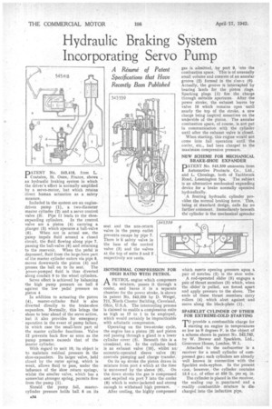
A Résumé of Patent Specifications that Have Recently Been Published
DATENT No. 543,418, from L. 1 Coatelen, St. Ouene France, shows an hydraulic -braking system in which the driver's effort is normally amplified by a servo-motor, but which retains direct human actuation as a safety measure.
Included in the system are an enginedriven pump (1), a two-diameter master cylinder (2) and a servo control valve (3). Pipe 11 leads to the shoe expanding cylinders. In the control valve are a piston (4) carrying a plunger (5) which operates a ball-valve (6). When not in actual use, the pump impels fluid around a closed circuit, the fluid flowing along pipe 7, passing the ball-valve (6) and returning to the reservoir. When the pedal is depressed, fluid from the large-bore part of the master cylinder enters via pipe 8, moves downwards the piston (4) and presses the ball on to its seat. The power-pumped fluid is thus diverted along conduit 9 to the wheel cylinders.
Servo effect is achieved by balancing the high pump pressure on ball 6 against the low pedal pressure on piston 4 In addition to actuating the piston (4), master-cylinder fluid is also diverted directly to the brake-shoe expanders. Normally, this brings the shoes to bear ahead of the servo action, but it also provides for emergency operation in the event of pump failure, in which case the small-bore part of the master cylinder functions. Valve 12 prevents back flow so soon as the pump pressure exceeds that of the master cylinder.
With regard to unit 10, its object is to maintain residual pressure in the shoe-expanders. Its larger valve, held closed by the outer spring, which is weak, allows fluid to pass, tinder the influence of the 'shoe return springs, whilst the smaller valve, which has a somewhat stronger spring, permits flow from the pump (1).
Should the pump fail, mastercylinder pressure holds ball 6 on its seat and the non-return valve in the pump outlet prevents escape by pipe 7. There is a safety valve in the base of the control valve (3) and the valves at the top of units 3 and 2 respectively are vents.
ISOTHERMAL COMPRESSION FOR HIGH RATIO WITH PETROL
A PETROL engine which compresses rt its mixture, passes it through a cooler, and burns it in a separate chamber for the power stroke, is shown in patent No. 543,359 by D. Weigel, 711, Ninth Chester Building, Cleveland, Ohio, U.S.A. The intercooling process is claimed to enable a compression ratio as high as 17 to 1 to be employed, which would certainly be impracticable with adiabatic compression.
Operating on the two-stroke cycle, the engine has a piston (3) and piston rod passing through a gland in a lower cylinder cover (5). Beneath this is a crosshead, etc. In the cylinder head is an exhaust valve (10), whilst an eccentric-operated sleeve valve (6) controls pumping and charge transfer.
On its up stroke the piston draws in mixture from port 4 which at the time is uncovered by the sleeve (6). On the down stroke the gas is compressed and expelled via port 7 into the cooler (8) which is water-jacketed and strong enough to withstand high pressure.
After cooling, the highly compressed gas is admitted, by port 9, into the combustion space. This is of unusually small volume and consists of an annular groove (2) formed in the sleeve (6). Actually, the groove is interrupted by bearing lands for the piston rings. Sparking plugs (I) fire the charge through suitable apertures. After the power stroke, the exhaust leaves by valve 10 which remains open until nearly the top of the stroke, a new charge being inspired meantime on the underside of the piston. The annular combustion space, of course, is not put in communication with the cylinder until after the exhaust valve is closed.
When starting, this engine would not come into full operation until the cooler,. etc., had been charged to the maximum. compression pressure.
NEW SCHEME FOR MECHANICAL BRAKE-SHOE EXPANDER
PATENT No. 543,339 emanates from Automotive Products Co., Ltd., and L. Chouings, both of Tachbrook Road, Leamington Spa. The subject is an alternative mechanical expanding device for a brake normally operated bych aulically.
A floating hydraulic cylinder provides the normal braking force. This, being of standard design, calls for no further comment. Immediately beneath the cylinder is the mechanical spreader which exerts opening pressure upon a pair of notches (2), in the shoe webs.
A rod-operated slider (5) engages a pair of thrust members (3) which, when the slider' is pulled, are forced apart and apply pressure to the shoes. The ends of these thrust members carry rollers (4) which abut against and move along the black-plate (1).
SPARKLET CYLINDER OF ETHER FOR EXTREME-COLD STARTING e provide a, combustible charge for V:tailing an engine in temperatures as low as 0 degrees F. is the abject of a scheme shown in patent No. 542,743, by W. Brewer and Sparklets, Ltd., Grosvenor House, London, W.1.
Attached to the carburetter is a receiver for a small cylinder of compressed gas ; such cylinders are already well known in connection with the Sparldet soda-syphon. In the present case, . however, the cylinder, contains 13.5 c.c, of ether at 550 lb. per sq. in.
The cylinder is placed in the receiver, the sealing cap is .punctured and a readily combustible mixture is discharged into the induction pipe.