


Patents Completed.
Page 22
If you've noticed an error in this article please click here to report it so we can fix it.
Complete specifications of the following patents will be sent to any address in the United Kingdom by the Sales Branch, Patent Office, Holborn, W. C., upon receipt of eightpence per copy.
The Latest Mileage Recorder.
The Metropolitan Fare Register Co., Ltd., and A. Bailey, No. 6193, dated 12th March, 1912.—One of the special featurea of the counting mechanism described in this specification is that the units drum is driven by a star wheel mounted eccentrically on the shaft and controlled by two pins fixed in a bracket in the castni.:. The motion given to this
eccentric wheel is such that, during the upper half of its revolution, its teeth engage and drive the first wheel of the train, but during the other half of the revolution the teeth do not, drive but are only lightly engaged. This engagement is sufficient to hold the first member of the train, which is the units drum, from being shifted by the vibration of the vehicle or otherwise. The recorder is operated through a worm drive and a ratchet and pawl, so that no record is made when the vehicle is run backwards.
.JA Cash-register Taximeter,
The Premier Taximeter Co., Ltd. A. Schneider), No. 5330, dated 2nd March, 1912.—This invention relates to taximeters of the kind in which the total amount registered is printed on a strip of paper or a card. Such cards can be placed into position by the proprietor of the vehicle, and the object of the invention is to provide mechanism which wil prevent the driver ascertaining this re cord, or tampering with the dials b2, which it is registered. A cam is fixed on the flange spindle, and engages a lever which, when the flag is turned into the engaged position, lifts a vertical member which carries the printing plate. In one position of the operating lever, a plate at the bottom of the meter is moved towards the right so as to bring a slot in it, M register with a slot in a fixed plate, so allowing the card or paper to be inserted through the slots on to the printing plate adjacent to the printing discs. The operating handle is then turned a little further, and the printing plate is moved forward so as to cause an impression to be made. On the release of the operating handle, the spring draws the printing plate up, and all the other parts back into their normal position. The operating lever tan be locked in any suitable manner by the proprietor of the vehicle.
Rim and Tire Lightness.
A. C. Stevenson, No. 4725, dated 26th February, 1912.—This specification describes a novel construction of a wheel and rim in which the weight is considerably reduced and the ease of attaching a tire is increased. The actual rim on the wheel lies in the same plane as the spokes, and the tires are vulcanized directly on to an ordinary rim. This is provided with an inwardly extending flange, which may be either at one side or in the middle of the tire rim, and which is bolted direct on to the radial rim on the wheel. It will be seen that the tire itself overhangs the wheel, and its rim is made sufficiently strong to allow of this. When applied to twin tires this construction renders it possible to remove them both on the same ski,' of the wheel.
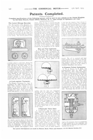
A Hydraulic Valve Gear.
F. Lamplough, and D. Napier and Sons, Ltd., Nu. 20,953, dated 13th September, 1912.—The special feature of this invention is that no air chamber is used in maintaining the pressure of the fluid by which the valves are operated. The accompanying drawing shows the controlling and operating mechanism, which is provided with a continuouslydriven rotary pump on the right-hand side. This pump is mounted on a shaft which also forms the distributor. The shaft is hollow, and oil under pressure is fed into the interior, from whence it passes, by means of ports, into c.onduite leading to the various valves to be operated. The rotation of the shaft brings these ports in turn opposite the proper conduits. The release of the valves is effected by connecting their conduits with an annular chamber in the distributor, by means of ports. This chamber is open to the suction side of the pump, so that a continuous flow of oil is main
tamed. The oil is retained and kept under pressure in the interior of the distributor by a relief valve. This is suitably loaded to allow the pump to work continuously; operation of the valves is therefore immediate and certain.
A ;Clement-Talbot Carburetter.
G. W. A. Brown, G. P. Mills, and Clement-Talbot, Ltd., No. 4695, dated 24th February, 1912.—This specification describes a carburetter of the type shown in Patent No. 21,752/1910, in which the air valve is held on its seat by its own weight, and is lifted by the suction of the engine. The mixing chamber above the air valve is in communication with the air and the fuel inlet. The latter is a vertical tube, by which the petrol is sucked from a float chamber at the bottom of the carburetter. Air passages are provided to convey some of the air immediately over the opening of the jet tube. Previously the throttle valve was seti as the atomizer, but it is found that at high speeds this is not sufficient, and a baffie plate is therefore provided immediately over the jet.