


MACHINE TOOLS FOR THE MOTOR INDUSTRY.
Page 17
Page 18
Page 19
If you've noticed an error in this article please click here to report it so we can fix it.
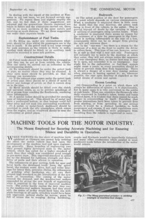
The Means Employed for Securing Accurate Machining and for Ensuring Silence and Durability in Operation.
-WHEN VIEWING the fine. show of machine tools exhibited at Olympia one cannot help noticing the effect the motor vehicle has had upon the development of the machine tool and upon engineering generally. Many branches of engineering owe their present highly developed state to the motor vehicle, which has called for a higher standard of work than that which was considered good enough in pre-motor days. This improved standard is called for by the demand for lightness, strength and durability of parts and their silence in operation.
The refinements of gear cutting, both for spur and bevel teeth, the developed tooth form, the spiral bevel, the modern worm drive, ball and roller bearings for heavy duty, precision chains, the refinements of grinding after hardening, etc., all owe their present high standard to the introduction of the new mode of locomotion. The coming of the motor created the demand, and the machine-tool makers responded by giving the new branch of engineering what it required in the form of improved machine tools. The public hardly realize the debt they owe to the machine-tool makers, because, had they stood still, the motor of to-day would have been one with nlain bearings in all parts, cylinders would have been left unground, splined shafts be untrue, gears be full of errors due to warping during hardening, cranks and flywheels would be imperfectly balanced. and many other crudenesses which existed in most machinery made before the introduction of the motor would remain. The importance of silence in the pleasure car has been recognized from the beginning, but until recently it was not, recognized as an essential feature of the commercial motor vehicle. This was a mistake, as silence of running is often a very important factor while competing for an order, as the intending purchaser will argue, an& rightly too, that, if things are working silently, they are working with the least possible wear and tear.
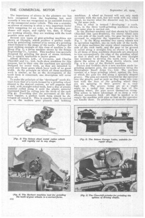
Several new types of gear-grinding machines are shown at Olympia, which. produce a perfect toothform by generating, instead of by means of a grinding wheel formed to the shape of the tooth. Perhaps the most striking example of this class of machine is the iliziag (Fig. 1), a Swiss machine shown by the Selson Engineering Co., London. This machine was specially designed for grinding the gears of steam turbines, but is equally applicable to motor gears.
, Alfred Herbert, Ltd., of Coventry, and Charles Churchill and Co., Ltd„ both show machines for this purpose, but in their case the machines are specially designed for motor work, as they are intended to grind only those gears which have teeth of no great width.. As the prineiple on which all these machines work is similar, so far as the development of the tooth form is concerned, one description will cover them all.
To make the principle of the "developed" tooth distinct from that of a tooth formed by a grinding wheel shaped to the desired contour, we will suppose that a rack, with straight-sided teeth, had a disc of plastic material rolled along it until the plastic material impressed itself by roiling into the teeth of the rack (Fig. 2). Providing that the movement of the disc were regular, a perfect tooth form would be developed all round it. This is exactly -what is carried out in the modern gear planers and hobbing
machines. A wheel so formed will not only mesh correctly with the rack, but will mesh with any other, wheel, no matter what the diameter may be, formed by the same rack.
This is what is termed " developing a tooth.. Now,. in the three tooth-grinding machines shown, this same plan is carried out.
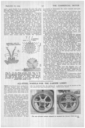
In the Herbert machine and that shown by Charles Churchill (the Lees-Bradner), the emery wheel acts on one side of the tooth only, the gear having to be reversed to complete the operation as shown in Fig. 7. In the Maagmachine two emery wheels are in operation together, one on each side of the tooth. In all three machines the emery wheel represents the side of the rack teeth, and the gear to be ground is rolled along a straight line as shown in Fig.
In all three of these machines diamonds are employed to true automatically the edge of the grinding wheel so that it shall not depart from the true straight line necessary to develop the tooth form. Fig 6 shows the action of the Illaag double wheels, and Fig. 4 is a view of the Herbert machine.
Burton and Griffiths show a new machine made for grinding gudgeon pins, the manufacturers being the Birmingham Small Arms Co., Ltd. The machine consists of a large grinding wheel, against the face of which the pins are fed along a specially shaped groove. The pins are merely inserted by the operator into the groove, and so soon as they come into contact with the face of the grinding wheel they are set spinning in their groove at a very high rate. The groove being set at a slight angle to a radial line across the face of the grinding wheel, the pins screw themselves along. This action is taken advantage of to form a very efficient automatic feed. All that is needed is to supply the machine with pins as fast as the operator can handle them. To produce an accurate diameter and a good finish it is necessary to pass the pins through many times, but even then the operation is far quicker than grinding each pin separately. The Olsen-Carwen static dynamic balancing machine is shown by Edward Herbert, Ltd., of Manchester. This machine will not only indicate errors of a standing or static balance, but will show the amount and locality of any unbalance which may exist in a crank or fly wheel. To make the difference between static and dynamic balance clear, let us consider a crankshaft with two heavy places, at opposite sides of the centre line and even in weight, but not directly opposite each other. Such a crank would balance evenly if laid on two level and straight edges, but in running at a high speed it would set up considerable vibration, because the heavy places are not opposite to each other. Such a crank would be in correct static balance, but in incorrect dynamic balance. The Olsen-Carwen machine is designed to detect such errors and to enable the operator accurately to determine the exact amount and position of such errors.
We are of opinion that the matter of balance has been somewhat neglected by the makers of commercial motors, and we should welcome the more general installation of up-to-date balancing machines.
A very useful tool for cutting sheet metal such as that used for tank, mudguard and body making is shown in Fig. 2. In this machine an eccentric with a very small throw is driven at a high rate of speed by means of an electric motor. The eccentric imparts a very small amount of movement to the top blade of the shears shown. So slight and rapid is the movement that, to a casual observer, the blade might be thought to be stationary. The sheet to be cut can be manipulated with the greatest ease, and curved lines as well as straight ones can be cut. This machine is known as the Lightning cutter, and is handled by the Selson Engineering Co.
Many good examples of lathes suitable for garage work and for the maintenance of fleets of vehicles are shown. Drummond Bros., of Guildford, show many useful appliances by which a lathe can be used for milling and other jobs. For the maintenance of a fleet of heavy vehicles it is essential that a good lathe, well up to its work, should be installed.
In the usual outfit seen in such garages the idea seems to linger that any old lathe is good enough for the occasional jobs that may come along. This, however, is a great mistake, and one that usually results in many jobs being given out whereas they might have been done in the garage had the equipment been more efficient.
Among the lathes exhibited that shown in Fig. 3 struck us as being ideal for the maintenance of heavy vehicles. It might be said that an all-gear head is a luxury, but it must be remembered that, in the usual garage, there is not often any structure to which an overhead motion can be fixed. The one shown is a thoroughly efficient lathe at a moderate price. A finaaller pattern is made, but without the all-geared head. These lathes are shown by the Selson Engineering Co.
The Britannia Lathe and Oil Engine Co., of Colchester, show some very useful flow meters for use in the test shop and in the dash. They can be sunplied-for any fluid, petrol or lubrication oil, and will indicate the most, minute flow.
The British Oil and Turpentine Corporation show a new lubricant suitable for the gearboxes of motorcars and cycles. It is claimed for this lubricant that it is possible to keep the outside of a gearbox cleaner than with other lubricants.