


For Protecting Track-wheel Bearings
Page 44
If you've noticed an error in this article please click here to report it so we can fix it.
A Resume' of Patent Specifications that Have Recently Been Published
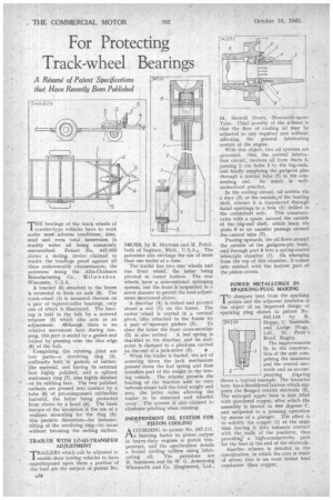
THE bearings of the track wheels of crawler-type vehicles have to work under most adverse conditions, dust, mud and even total immersion, in muddy water all being commonly encountked. Patent No. 547,033 shows a sealing device claimed to render the hearings proof against all these unfavourable circumstances, the patentees being the Allis-Chalmers Manufacturing Co., Milwaukee. Wisconsin, U.S.A.
A bracket (5) attached to the-frame is extended to form an axle (9). The track-wheel (1) is mounted thereon on a pair of tapered-roller bearings, only one of which is illustrated. The bearing is held in the hub by a screwed retainer (2) which also acts as an adjustment. Although there is no relative movement here during .running, this part is sealed by a gasket and locked by peening over the thin edge (8) of the hub.
Comprising the running joint are two parts—a revolving ring (3), resiliently held in gaskets of rubberlike material, and having its external face highly polished, and a spline(' stationary ring (7), also highly finished on its rubbing face. The two polished surfaces are pressed into contact by a tube (6) of pre-compressed rubberlike material, the latter being protected from above by a hood (4). The basic feature of the invention is the use of a resilient mounting for the ring (3); this permits distortion—for instance, tilting of the revolving ring—to occur without breaking the sealing surface.
TRAILER WITH LOAD-TRANSFER ADJUSTMENT
TRAILERS which can be adjusted to enable their towing vehicles to have superimposed upon them a portion of the load are the subject of patent No.
A34 546,824, by R. Harroun and M. Pribil, both of Saginaw, Mich., U.S.A., The patentees also envisage the use of more than one trailer at a time.
The trailer has two rear wheels and one front wheel, the latter being pivoted in castor fashion. The rear wheels have a conventional springing system, but the front is suspended in a novel manner to permit the load adjustment mentioned above.
A drawbar (4) is forked and pivoted about a rod (1) on the frame. The castor wheel is carried in a vertical pivot, also attached to the frame by
a pair of 'upswept girders (5). To clear tje latter the front cross-member (2) is also arched. A leaf spring is shackl d to the drawbar, and its midpoint Is clamped to a platform carried
on the end of a jack-screw (3). •
When the trailer is loaded, the act of screwing down the jack mechanism press0 down the leaf spring and thus transfers part of the weight to the towing vehicle. , The scheme permits the loading of the tractive unit to vary between about half the total weight and zero, the latter value allowing the trailer to be detached and wheeled away. The system is also claimed to eliminate pitching when running.
INDEPENDENT OIL SYSTEM FOR PISTON COOLING
ACCORDING to patent No. ,547,111, ./–ta limiting factor to power output in heavy-duty engines is piston temperature. and the specification details a forced cooling syitem using -lubricating oil. The patentees are H. Sammons and Sir W. G. Armstrohg Whitworth and Co. (Engineers), Ltd.,
24, Stowell Street, Newcastle-uponTyne. Chief novelty of the scheme is that the flow of cooling oil may be adjusted to any required rate without affecting the general lubricating system of the engine.
With this object, two oil systems are provided. One, the normal lubrication circuit, receives oil from ducts 4, passing it via holes 2 to the big-ends, and finally supplying the gudgeon pins through a central tube (7) in the connecting rod. So much is wellunderstood practice.
In the cooling circuit, oil arrives via a duct (3) at the outside of the bearing shell, whence it is transferred "through facial openings to a hole (5) drilled in the crankshaft web. This communicates with a space, around the outside of the big-end shell, which leads via ports 6 to an annular passage around the central tube (7).
Passing upwards, the oil flows around the outside of the gudgeon-pin bush, and through port 8 into a spring-seated telescopic chamber (1). On emerging from the top of this chamber, it comes into contact with the hottest part of the piston crown.
POWER METALLURGY IN SPARKING-PLUG MAKING .TO dissipate heat from the sparking 1 points and the adjacent insulator isthe object of an improved design of sparking plug shown in patent No. 547,119 by B. Hopps, C. Stnithelli and Lodge Plugs,' Ltd., St. Peter's Road, Rugby.
The improvements lie in the construction of the unit comprising the insulator and the central electrode and an accompanying. dr-4wing shows a typical example. The insulator bore has a shouldered bottom which supports the flanged central electrode (21. The enlarged upper bore is first filled with powdered copper, after which the assembly is heated to 950 degrees C. and subjected to a pressing operation by means of a plunger. The effect is to solidify the copper (1) at the same time forcing it into intimate contact with the walls of the insulator, thus providing' a high-conductivity path for the heat at the end of the electrode..
Another scheme is detailed in the specification, in which the core is made of silver; this is an even better heat conductor than copper.