


A SWASH-PLATE INTERNAL-COMBUSTION ENGINE.
Page 32
If you've noticed an error in this article please click here to report it so we can fix it.
A Resume of Recently Published Patents.
THE APPLICATION of the piinciple of the swash-plate to
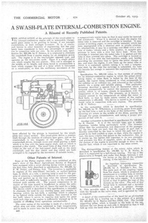
the internal-combustion engine and to automobile changespeed gears seems to be growing in favour, if note amongst constructors, at least amongst. inventors. It is, of course, well known in -other branches of engineering, but has only lately been Considered to have any advantages or possibilities in connection with our own. In the present case, specification No, 203,146, by P. Salmon, it is employed to eliminate the crankshaft from a starter engine for an aeroplane power unit. The engine is of the two-cylinder opposed type, and operates on the two-stroke cycle. There is a single piston rod, which couples the two pistons. This rod is enlarged in the middle of its length, and there bored to accommodate a bush which engages the end of a lever which is fulerumed on a swash-plate, so that the oscillatory movement of the lever effected by the pistons is translated by the swashplate into rotary motion. The swash-plate drives a countershaft through the medium of ordinary spur ears, and on the countershaft is the magneto of the engine. The same countershaft drives, through worm and wheel gearing, a shaft which is in line with the main engine shaft, and on which is mounted a disc clutch. The usual form of dog clutch is provided on the end of the last-named shaft and on the main crankshaft, and the disc clutch and dog clutch are both arranged to be engaged by the movement of suitable levers.
Other Patents of Interest.
Some of the Better engines which were exhibited at this year's show of the Royal Agricultural Society of England were equipped with a novel starting device which is now, for the first time, fully described in specification No. 203,524, by P. W. Fetter, and Betters, Ltd. The invention is applicable to engines of the semi-Diesel, hot-bulb, or surface-ignition type, in which, as a rule, a starting lamp is used for the purpose of attaining a temperature sufficient to ensure .vaporization and ignition up to the time when the internal surface of the bulb is sufficiently heated to carry on the combustion without such outside aid. The normal compression in an engine of the type named is insufficient to secure the automatic vaporization of the fuel oil, hence the need for a lamp. The device which is described in this specification is intended to eliminate the need for any starting lamp, and consists in burning, within the hot bulb, a cartridge which is adapted to be lighted while outside the engine, then inserted in the hot bulb, where it serves to vaporize and ignite the gases until such time as the engine is sufficiently warmed up to be capable of effecting those operations automatically.
The outer casing of the cartridge is made of a metal alloy, which does not scale when subjected to high temperatures, and is made to screw into the hot bulb, the thread being of E48 ,
a comparatively coarse type, so that it may easily be inserted and withdrawn. When it is desired to start the engine the metal tube is removed and" the cartridge is inserted. It may consist of blotting paper, or some similar material, which has been impregnated with a chemical such as nitrate solution,. or, alternatively, it may be a cartridge case filled with a mixture of tinder, nitrate and a little sulphur, in suitable proportions to burn With a. slow but fierce heat. When this cartridge is inserted into the metal tube it is ignited and the tube is then screwed into place. The cartridge is located so that it is in line with the fuel-injection nozzle, and, besides providing the necessary heat. to' ignite the initial charges of gas, and start the engine, it also heats up the metal tube in which it is contained, quickly raising it to such a temperature that, by the time the cartridge is exhausted, the tube has become hot enough to maintain, the explosions within the engine.
Specification No. 203,152 refers to that system of cooling for an internal-combustion engine in which the actual circulating water, or other fluid, • is boiled by the heat Of the engine, the vapour being condensed in what corresponds to the radiator on an ordinary car, and returned to the cylinder jackets via a pump and suitable piping. This particular invention describes a special form of thermostat which is designed automatically to control the pressure within the system, which is, of course, closed, in -accordance with the temperature of the engine. The pressure, as is known, is directly related to the temperature at which the water or fluid boils, so that by these means control of the engine temperature is afforded. The device is stated to be of exceptional value in connection with aero engines. The patentee is H. C. Mallory.
In the carburetter which is described in specification. No. 202,670, by W. WPeritmore, a revolving gauze drum picks up the fuel from a well in the body of the carburetter. The incoming air enters in the middle of the drum, passing out through the gauze circumference, and taking a proper proportion of fuel with it.
Another carburetter is described in specification No. 182,810., by E. Feroldi. It is of the two-fuel type, and is rather ingenious besides being particularly novel. The inventor claims that the construction and dimensions of the passag6s for the two fuels are such that the supply of each fuel is directly controlled by the heat to which the said fuel is exposed in its feed conduit or pipe, so that, while the engine is cool, the more volatile fuel passes to the carburetter, hut, as it warms up, the lighter fuel vaporizes in its own passages. and prevents the flow of supplies, while, at the same time, the suction of the engine is powerful enough to draw on the heavier fuel, which is not vaporized to the same extent.
The distinguishing feature of the rotary valve which is described in specification No. 189,460, by T. R. Muller, is that it is supported by a ball-thrust bearing. The top of the i sleeve-valve s flanged, and under that flange, between it and the facing on the top of the cylinder casting, is-the ball-thrust race.
An ingenious tyre-pump connection is described in specification No. 184,149, by A. Schiader's Son, Inc. The main part of the coupling—apart from 'the shank, which is prepared for attachment to a rubber hose or similar connection—is bored to pass over the end of the valve nipple. It is smooth bored so that it-passes the tops of the threads on the valve. The wall of this bored hole is recessed and a movable catch is made to project through movable catch is milled and grooved to engage threads on the valve stem, and is operated by hand as required.
A detail of the construction of the hood for an all-weather type of body for a touring car is the subject of a patent, No. 203,473, by G. Beaton and Son (1919), Ltd. The vertioal supporting pillar, which is located, on the body of the ear, between the two doors on each side is designed so that it will fold up with the hood when it is stowed away. it. This with the