


THE BREED OF • THE COAC W IT IS BEING. IMPROVED.
Page 16
Page 17
Page 18
Page 19
If you've noticed an error in this article please click here to report it so we can fix it.
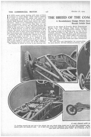
IN OUR recent article dealing with some of those problems in coach .design which require solution in order to promote the safety and comfort of the passengers, we gave what, in our opinion, constitute those features which must receive the fullest attention. Some of our suggestions were of a somewhat revolutionary nature, but that they are not impracticable is proved by the fact that during the whole of the past year a chassis which embodies certain of these details, as well as other startling innovations, has been in process of manufacture, and it is only now that we have received permission to publish illustrations and details of what, in our opinion, is perhaps the most remarkable chassis ever built.
It is fairly usual to be able to point to some particularly interesting feature on a chassis of new design, but it is quite exceptional to be able to deal with a new model in which at least half a dozen of the leading features are quite out of the ordinary.
The chassis of which we write is one nearing COM
pletion in the shops of French's Motor Engineering Works, Ltd., 279, Balham High Road, London, S.W. 17. It is of an experimental nature, in that the leading points in its design may or may not be retained, according to the result of the experience gained with them. Some of them apply more particularly to the private car, whilst others are essentially features which should prove of very considerable value in connection with coach and other commercial vehicle chassis.
We will start our description by enumerating the main details. All four wheels are driven, and, as the hand and foot brakes act through the transmission, the braking is also on all wheels. There are no axles in the true sense of the word. The steering can be on all wheels, or on the front only, whilst a simple but novel device permits crab steering when required. The springs are self-adjusting to speed, and the frame is of pressed girder construction. The braking is so arranged that at slow speeds the pull is through a spring, and is, therefore, gradual, whilst at high speeds this spring is automatically cut out. • Incidentally, the shoes are hollow and are watercooled, thus greatly increasing their life.
We would emphasize the point that, although at present built as a light chassis, it is only for convenience in manufacture, and, as our description is followed, it will be seen that if the design proves satisfactory for pri'vate car purposes it should be many times more valuable for commercial vehicle work.
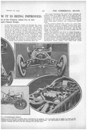
In the present chassis the engine is a four-eytindered Asizani with an ordinary leather-faced cone clutch driving through to a Wrigley four-speed gearbox of the new standard Kent type. So far the design is normal, but now we come to what may be called the abnormal.
From the gearbox the drive is taken through a Hardy disc joint to a further unit known as the distribution box. This is quite compact, and consists of an aluminium casing enclosing a central differential gear of the four bevel pinion type which is driven by spiral bevels. On each differentia) shaft is a small spiral-bevel crown wheel, and with. each crown
wheel mesh two bevel pinions, one on each of the two propeller shafts, leading to the front and rear Wheels respectively.
Each propeller shaft and pinion is formed solid, and has two plain bearings in an extension arm bolted to the distribution box. On the outside of each of the extension arms is fitted a forked forging, which houses the two ball joints for what are known as the duplex tubes. The upper of these tubes forms a cming for the continuation of the propeller shaft, whilst the lower provides a parallel motion, which ensures that the steering pin is always vertical. The two tubes also act as radius rods. The fork itself is spring-loaded, so that direct shocks from each wheel are taken care of. The actual movement permitted is tin. in either direction.
In a direct vertical line with the duplex tube ball joints is a universal joint on the driving shaft, whilst at the other end, at the centre of the steering pin, is a further universal joint. The crown wheel for driving each road wheel is housed on the hub, whilst the pinion is carried by the rear portion of the stab. axle in a long plain bearing immediately in front of the pinion, which, at its rear, is provided with a large doublethrust race.
The steering pin is divided, each half being keyed, and a driving fit into the top and bottom of the stub axle respectively.
Now we come to the very novel method by which the chassis is sprung, and by which the axles proper are dispensed with.
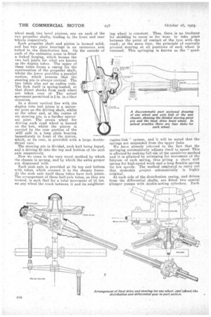
Each stub axle is provided at its top and bottom with tubes, which connect it to the chassis frame. At the stub, axle itself these tubes have fork joints. The arrangement of these half-axle tubes, as they are termed, is such that for a total movement of 12 ins. en any wheel the track between it and its neighbour
ing wheel is constant. Thus, there is no tendency for skidding to occur or for wear to take place between the point of contact of the tyre with. the road ; at the same time, the principle of centrally pivoted steering at all positions of each wheel is retained. This springing is known as the " quad ruplex-link " system, and it will be noted that the springs are suspended from the upper links. We have already referred to the fact that the springing automatiCally adjusts itself to speed. This is effected by making full use of the cantilever method and it is attained by arranging for movement of the fulcrum of each spring, thus giving a short stiff spring for high-speed work and a long flexible .spring for low speeds. The method employed to carry out this desirable . project automatically is highly original. At each side of the distribution casing, and driven from the differential shafts, are fitted two special plunger pumps with double-acting cylinders. Each pump delivers oil via a variable-orifice venturi valve to one of the spring dashpots, which is connected' to -a slipper provided with steel rollers which forms the fulcrum of. this particular spring. Now, if the pressure in each dashpot be increased, its corresponding slipper is forced along a special slide attached to the frame, and thus shortens the effective length of the spring. As the pressure decreases so the fulcrum slipper is drawn back and the spring rendered more flexible. Owing to the pumps being direct-driven, their speed varies with that of the vehicle, and thus the dashpot action also varies in the same manner.
There is a control on the dash by which the orifices of the venturi valves can be altered, and thus the spring action may be adjusted to various loads.
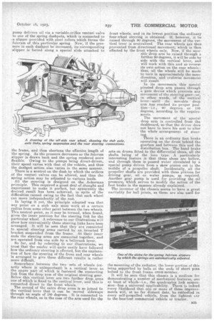
All the steering is designed on the Ackerman principle. This required a great deal of thought and experiment to make it pekrfeet, but apparently the desired result has been achieved, in spite of the difficulties caused owing to the fact that each wheel can move independently of the rest.
In laying it out, the principle adopted was that any point on a stub axle must work at a certain radius from some other point between the two wheels. This neutral point, as it may be termed, when found, gives the inner position for the steering link for the particular wheel. A reference to our illustrations will show how conveniently these steering links have been arranged. It will be seen that they are connected to special steering arms carried by an inverted T bracket suspended from the frame. At their inner ends the steering arms are connected together, and are operated from one side by a bellcrank lever.
So far' and by referring to our illustrations, we trust that, the reader will quite easily have followed how the ordinary steering is effected, but the explanation of how the steering of the front and rear wheels is arranged to give three different results is rather more difficult.
Somewhere between the two sets of wheels (exactly where is unimportant) is a vertical lever to the upper part of which is fastened the connecting link from the drop arm of the original steering gear. Below this vertical lever are two further drop arms one of which is fixed to the vertical lever, and this is connected direct to the front wheels.
The second of the extra drop arms is so joined to the vertical lever that it can be moved sideways through an angle of 180 degrees. It is connected to the rear wheels, as in the case of the arm used for the
front wheels, and in its lowest position the ordinary four-wheel steering is obtained, if, however, it be raised through 90 degrees, the movement of the vertical lever is neutralized. The rear wheels are thus prevented from directional movement, which is then effected by the front wheels only. Now, if the movable drop arm he raised through a further 90 degrees, it will be side by• side with the vertical lever, and will work with this and so reverse its own action on the rear wheels ; thus, all the wheels will be made to turn in approximately the same direction, and crabwise movement
will result. _ In its movements this special pivoted drop arm passes through a gate device which prevents any movement of the steering gear—or, in other words, of the vertical lever—until the movable drop arm has reached its proper Position—i.e., 90 degrees or 180 degrees, according to the requirements.
The movement of the' special d.rop arm is controlled from the dashboard, so that the driver does not have to leave his seat to alter the whole arrangement of steering. There is an ordinary foot brake operating on the drum behind the gearbox and between this and the distribution box. The hand brake acts on drums fitted to the differential shoes, all the shafts being of the loco type. A particularly interesting feature is that these shoes are hollow, and through them is passed water circulated by a special pump driven from a skew pinion cut ie the middle of a propeller shaft. Incidentally, all the propeller shafts are provided with these pinions for driving gear, oil or water pumps, as required. Another gear pump is used, for providing the oil pressure, which serves to modify the action of the foot brake in the manner already explained.
The inventor of the chassis seems to-have a great Partiality for ball joints, as these are also need for the mounting of the radiator, the lower portion of this being supported by balls at the ends of short pins bolted to the front frame cross member. •
It will be seen that this chassis is a medium for demonstrating a number of mechanical features, one at least of which—i.e., the quadruplex link suspension—has a universal applicability. There is indeed every likelihood that one or more of these improvements will, at no far distant date, be enebodied in every self-propelled vehicle, from the lightest car to the heaviest commercial vehicle or tractor.