


A Liquid-damped Rubber Spring • A NOVEL resilient member for use in
Page 78
If you've noticed an error in this article please click here to report it so we can fix it.
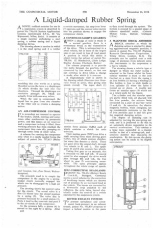
a suspension system is described in patent No. 756,416 (Societa Applicazioni Gamma Antivibranti S.P.A., 88 Via Ripamonti, Milan, Italy). It consists of a single member embodying a steel spring, a rubber spring and a liquid damping device.
The drawing shows a section in which 1 is the steel spring and 2 a rubber moulding that also works as a spring. Moulded across the bore is a diaphragm (3) which divides the unit into two chambers. Through the diaphragm are restrictive passages (4), which are actually fitted with one-way valves.
When the unit is compressed, the liquid has to pass from one chamber to the other and so creates a damping action.
AN AIR-COMPRESSOR CONTROL IT is nowadays not unusual to operate the brakes, clutch, steering and sometimes other mechanisms by pneumatic power, and this means an air reservoir and a compressor to keep it filled. Once working pressure has been reached, the compressor then runs idly, pumping air through some form of relief valve.
A scheme for running the compressor only when it is really needed forms the subject of patent No. 757,613 (Maley and Taunton, Ltd., Zoar Street, Wolverhampton).
The principle used is to couple the compressor to the engine by a springloaded clutch normally engaged but which can be disengaged by a high air pressure.
The drawing shows the control valve for the clutch. The actual valve is a disc (1) biased into the closed position by a spring (2). The valve disc is pressure-balanced by a small piston (3). Ports 4 lead to the reservoir and port 5 to the air-clutch of the compressor.
As the pressure falls, a piston (6) is moved to the right by a spring. After B44 a certain movement, the snap-over lever (7) operates and the control valve moves into the position shown to engage the compressor clutch.
A CONTINUOUS-DRIVE GEARBOX
WHEN a change of ratio is made in a normal gearbox, there is a momentary break in the transmission of the drive. This is unimportant in a small vehicle, but in those of the largest sizes it can result in loss of road speed. A gearbox in which this defect is absent forms the subject of patent No. 758,516. (T. Hindmarch, Lindo Lodge, Stanley Avenue, Chesham, Bucks.)
The scheme proposed is to provide two paths through the gearbox, interconnected by free wheels, so that one can continue to drive while a change is made, after which it is overrun.
A diagrammatic view is shown in the drawing which illustrates two threeratio boxes in series, thus giving nine speeds overall. The input shaft (I)
carries three pinions (ABC) each of which contains a clutch for ratio selection.
Their mating gears (DEF) can drive a shaft carrying three more driving gears (GH1). two of which contain clutches; the wavy line denotes a clutch. These last gears drive the output shaft. through free wheels in K and L. The upper gears D and E also contain free wheels.
Taking first gear as an example, this is obtained via AD and GK. If second speed be also engaged, the drive would pass through BE and GK. the free wheel in gear D overrunning meanwhile. The same principle applies throughout the whole range of speeds.
SELF-CORRECTING HEADLAMPS
PATENT No. 756,124 (Robert Bosch G.m.b.H., Stuttgart, Germany) shows a novel scheme for the correction of headlamp beams which arc thrown out of position by an increased load in the vehicle. The beams are corrected by a bi-metallic strip attached to the reflectors, the strip being healed electrically under the control of a switch operated by the suspension system.
BETTER EXHAUST SYSTEMS
rr°prevent turbulence and consequent back-pressure in an exhaust system. patent No. 753.834 proposes to impart a helical motion to the gases
as they travel through the system. The motion is created by a special shape of exhaust manifold outlet. (Genera] Motors Corp., Detroit, Michigan U.S.A.) A MAGNETIC SHOCK ABSORBEll
1-1 A SHOCK absorber in which the
damping action is created by shear ing agglomerated magnetic particles, shown in patent No. 756,107 (Nationa Research Development Corporation, 1 Tilney Street, London, W.1). The principle can be applied over a with range of purposes from delicate scien. title instruments to the suspension el a heavy vehicle.
The drawing shows a vehicle type o, damper in which the outer casing attached to the frame whilst the !owe: tubular member is fixed to the axle Carried on a stem from the casing an iron bobbin (1) having a winding (2) The bobbin is free to slide inside as iron. cylinder (3) when the latter i: moved up or down. A double wal forms an annular space (4) which act: as a return path for the liquid.
The cylinder and the annular space are partly filled with oil charged witl fine iron powder, the mixture being circulated via a pair of one-way valve: (5 and 6).. In operation, the electro magnetic bobbin, when energized, set: up considerable resistance to the flov of iron particles past it and this give: the required damping action.
The degree of damping an be adjusted by varying the energizing cur rent, and it is preferred to do this bg an automatic device responsive to the vertical accelerations. This consists ol a large mass suspended in a manne: similar to that of a seismograph, and sensitive member that measures the acceleration. By this means, the damp ing action can be made to be slighth anticipatory.