


A•Swashplate Injection Pump
Page 70
If you've noticed an error in this article please click here to report it so we can fix it.
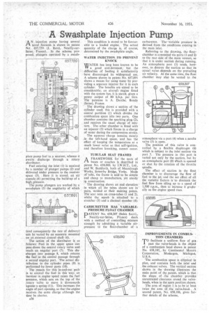
ANinjection pump having several novel features is shown in patent No. 657,759 (I. Retel, Seine, France). In the scheme proposed, plungers operated by a awash
plate pump fuel to a receiver, whence it awaits discharge through a rotary distributor.
Fuel entering the inlet (I) is received by a number of plunger pumps (2) and delivered under pressure to the receiver space (3). Here it is stored, an air capsule (4) permitting the build-up of a high pressure.
The pump plungers are worked by a swashplate (5) the angularity of which (and consequently the rate of delivery) can be varied by an eccentric mounted on an external control shaft (6).
The action of• the distributor is as follows: Fuel in the upper space can pass down the central rotary valve and reach an angular 'port (7). This discharges into passage 8, which returns the fuel to the central passage through
• a second angular port, The actual distribution to the cylinder pipes (9) is
• performed by lower ports (10).
The reason for this in-and-out path is to control the fuel in this way: an increase in engine-speed raises the fuel pressure, which acts on the top of the rotary valve to move it downwards against a spring (11). This increases the angle of port opening, so that the engine receives the same charge although the time be shorter,
*36
This condition is stated to be favourable to a loaded engine. The actual quantity of the charge is, of course, determined by the swashplate angle.
WATER INJECTION TO PREVENT KNOCK WATER has long been known to be VV a good anti-detonant,• but the difficulties of feeding it satisfactorily have discouraged its widespread use. A scheme shown in patent No. 657,891 shows a means for using water by providing a separate injector for it in each cylinder. The benefits are stated to be considerable; an aircraft engine fitted with the system has, it is stated, given a power output of 80 b.h.p. per litre. The patentee is A. Darche, Bondy (Seine), France.
The drawing shows a section of the cylinder used; this is provided with a central partition (I) which divides the combustion space into two parts. One chamber contains the sparking plug (2), and receives the usual charge of mixture. The other chamber is fitted with an injector (3) which forces in a charge of water during the compression stroke.
The aqueous charge remains mostly in the left-hand space, and has the effect of keeping the temperature at a much Tower value so that self-ignition, and therefore knocking, cannot occur.
TUBULAR SEAT FRAMES
A FRAMEWORK for the seats of tA buses or coaches is described in patent No. 658,000, by I.W.H.T., Ltd., and W. Barnforth, both of Mearclough Works, Sowerby Bridge, Yorks, Made of tube, the frame is said to be simple and cheap to manufacture, yet sturdy in construction.
The drawing shows an end elevation in which all the tubes shown are in pairs, welded at their meeting points. The seat rests on cross-tubes (1 and 2), whilst the squab is attached to a stretcher (3) and a channel member (4).
CARBURETTER HAS VARIABLEPRESSURE FLOAT CHAMBER
PATENT No. 658,207 (Solex S.a.r.1., Neuilly-sur-Seine; France) deals with a method of controlling mixture strength by admitting a variable airpressure to the float-chamber of a carburetter. The variable pressure is derived from the conditions existing. in
the main inlet. • • . • Referring to the drawing, the floatchamber is connected via ports (1 and2) to the rear side of the main venturi, so that it is under suction during running. An atmospheric port (3) tends, however, to destroy the suction so that its actual value depends on the prevailing air velocity. At the same time, the float chamber may also be vented to the a mosphere via a port (4) when a needle valve (5) is open.
The position of this valve is controlled by a flexible diaphragm (6) which is subject to the inlet suction via port 7. The pressure in this port is varied not only by the suction, but by an atmospheric port (8) ighich is opened or shut by the rotation of the throttle spindle, The effect of suction in the float chamber is to discourage the flow of fuel to the jet, and the net effect of all the variable factors is to diminish the fuel flow from idling up to a speed of 1,500 r.p.m., then to increase it gradually as the engine speed rises.
IMPROVEMENTS IN COMBUSTION CHAMBERS
TO facilitate a uniform flow Of gat
past the valve-heads is the object of a combustion head shown in -patent No. 658,185, by Continental Mcitciri Corporation, Muskegon, Michigan, U.S.A.
The combustion space is elliptical in plan, and contains both the inlet and the exhaust valves, The vertical section shown in the drawing illustrates the main point of the patent, which is that the shape of the chamber• provides unrestricted clearance round the valveheads, when in the open position shown: The area of region I is to be at least twice the area of the valve,head., A second patent, No. 658,186, gives further details of the scheme.