


• An Injection Pump for Petrol
Page 36
If you've noticed an error in this article please click here to report it so we can fix it.
THE possibilities of injecting petrol. instead of carburetting
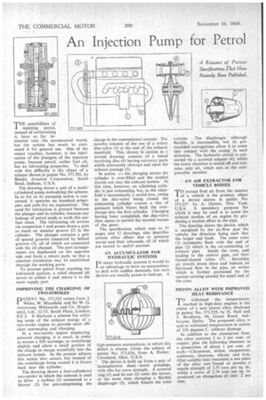
it, have so far in terested only the aeronautical world, hut the system has much to commend it for general use. One of the minor troubles, however, is the lubrication of the plungers of the injection pump, because petrol, unlike fuel oil. has no lubricating properties. To deal with this difficulty is the object of a scheme shown in patent No. 571,501, by Bendix Aviation Corporation, South Bend, Indiana, U.S.A.
The drawing shows a unit of a multicylindered pump embodying the scheme. In so far as its pumping action is concerned, it operates on standard principles and calls for no explanation. The need for lubrication is greatest between the plunger and its cylinder, because any leakage of petrol tends to wash this surface clean. The lubricating oil arrives via connection 1 and passes down a port to reach an annular groove (2) in the cylinder. The plunger contains a pair of spaced grooves connected by helical grooves (3), all of which are connected with the oil channel. The port arrangements are duplicated on the opposite side and form a return path, so that a constant circulation may be established through the working parts.
• To prevent petrol from reaching the lubricated portiOn, a relief channel (4) serves to collect it and returnit to the main supply port IMPROVING THE CHARGING OF TWO-STROKES
PATENT No. 571,525 comes from J. White, W. Mansfield, and Sir W. G. Armstrong Whitworth and Co. (Engineers), Ltd., 12-13, South Place, London, E.C.2. It discloses a scheme for utilizing some of the exhaust energy of a two-stroke engine to provide more efficient scavenging and chargine.
In a two-stroke engine employing pressure charging, it is usual, in order to ensure a full scavenge, to overcharge slightly and allow a small portion of the charge to escape wastefully into the exhaust system. In the present scheme this action also occurs, but instead of the overcharge being wasted it is blown back into the cylinder.
The drawing shows a four-cylindered two-stroke in which the exhaust is used to drive a turbine (I) connected to a blower (2) for pre-compressing the charge in the conventional manner. The .novelty consists of the use of a rotary disc-valve (3) at the end of the exhaust manifold. This, shown in section in a second drawing consists of a timed revolving disc (4) having cut-away parts which alternately obstruct and open the exhaust passage (5).
In action ca the charging stroke the cylinder is over-filled and the surplus travels out into the exhaust system. At this time, however, an adjoining cylinder is just exhausting, but, as the manifold is momentarily a sealed box, owing to the disc-valve being closed, the exhausting cylinder creates a rise of pressure which blows back the overcharge into the first cylinder. Charging having been completed, the disc-valve then opens to permit the normal escape of the gases
The specification, which runs -to 21 pages and 12 drawings, also describes certain other effects due to pressure waves and their rebounds, all of which are turned to useful account.
AN ACCUMULATOR FOR HYDRAULIC SYSTEMS I N many hydraulic systems it would be an advantage to have an accumulator to deal with sudden demands, but such devices are usually prone to leakage. A high-pressure accumulator, in which this defect is absent, firms the subject of patent No. 571,616, from A. Parker, Cleveland, Ohio, U.S.A.
" The device is built up from a pair of hemispherical sheet metal pressings, with ribs for extra strength. A screwed ring (I) and its nut (2) unite the halves, at the same time clamping a flexible diaphragm (3), which bisects the total volume. . The diaphragm, although flexible, is inextensible, but its premoulded corrugations allow it to come into contact with the casing in each direction. The hydraulic circuit is connected via a screwed adapter (4), whilst the lower chamber is sealed off and contains only air, which acts as the compressible member.
AN AIR EXTRACTOR FOR
VEHICLE BODIES
TO extract foul air from the interior of a vehicle is the primary object of a device shown in patent No. 571,257 by A. Decket, Ness York, U.S.A. A secondary purpose for which it may be used is to assist the exhaust strokes of an engine by pro. clueing a suction effect in the pipe.
The drawing shows the device, which is energized by the au-flow past the vehicle, the direction being such that the larger end leads. The outer cone (1) terminates flush with the end of pipe (2) which is the air-extracting or
exhaust pipe. Inside the cone, and leading to the central. Ripe, are four funnel-shaped tubes (3). Incoming air travels down these and induces an increased flow in the pipe, an action which is further promoted by the suction existing around the small end of the cone. .
PISTON ALLOY WITH IMPROVUD HEAT RESISTANCE
TO withstand the temperatures reached in high-duty engines is the object of a new -piston alloy disclosed in patent No. 571,529, by H. Hall and T. Bradbury, 96, Green Road, Ashbourne, Derby. The proposed alloy is said to withstand temperatures in excess of 350 degrees C. without damage.
In addition to the aluminium base, the alloy contains 2 to 3 per cent. of copper, plus the following elements in a proportion of about I per cent of eacht—Chromium, nickel, magnesium, antimony, titanium, silicon, and iron. After suitable heat treatment, a test piece of the alloy was found to possess a tensile strength of 3.55 tons per sq. in., whilst a stress of 2.74 tons per sq. in. produced an elongation of only .2 per
cent.