


ACCESSORY AND COMPONENT IMPROVEMENTS.
Page 30
If you've noticed an error in this article please click here to report it so we can fix it.
A Résumé of Recently Published Patents.
Current patent specifications are full of interest thie week, so much so that we have considered it advisable, for once, to depart from our usual practice of devote ing the hulk of our space to one leading invention, and, instead, have divided the intearest amongst several.
In view of the novelty of liquid fuel for steam wagons and the concrete example of this which was exhibited at the time of the ConunrerciaI Vehicle Show at Olympia, we will give pride of place to specification No. 151,671, by J. J. Kermode, which describes in some detail the application of a Hex/node pressure-jet burner to a steam wagon_ with a vertical boiler, such as that used on the Sentinel wagon. The inventor states that steam generators fitted with liquid fuel burners require a larger combustion chamber than is necessary for coal fuel. In order to obtain the necessary addition to the combustion space with the usual type of tubular vertical boiler, as fitted-to steam lorries, he preeides a cylindrical firebrick-lined easing, which depends: from the boiler proper and takes the place of the usual ashpart and grate. The burners are carried in a box on the side of this . casing, and the box is fitted with an air control, which is preferably in the form of a door hinged about apivot somewhat below the. centre of its area, the door being formed however with a weight at the bottom so that it is balanced about that hinge or pivot. The object of this arrangement is to ensure that, if for any reason_ the pressure within the furnace becomes greater than that of outside, as, for example, when a tube bursts, the door will automatically close.
The inventor is of opinion that the ordinary form of blast pipe fitted to steam wagons is objectionable when oil fuel is used. He suggests the use of a t-ubular ring, somewhat like an ordinary gas ring. This is placed inside the chimney with the jets projecting upwards, and it is fed by live steam.
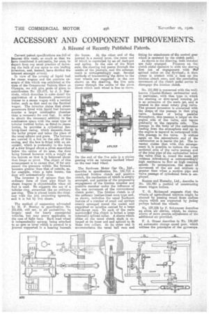
The method of suspension advocated by M. F. Huxley in specification No. 151,699, will not, in all probability, be largely used for heavy commercial vehicles, but may prove applicable in the case of light vans. Each road wheel is independently sprung, being attached to an sem or lever which is secured to a journal supported in a bearing beneath the frame. At the other end of the journal i5 a second lever, the outer end of which is controlled by an oil dash-pot and spring. In the ease of the front axle, the steering rod passes through the centre of the journals, and the arrangement is oorrespendingly neat. Several methods of transmitting the drive to the rear wheels are suggested : in the one shown. on the drawing, the live axle passes through the centre of the pivot about which each wheel is free to move.
On the end of the live axle is a pinion gearing with an internal toothed wheel on the rear read wheel.
The Sunbeam Motor Car Co-, IAA., deacrilbe ist pecification No. 151,713 a combined friction clutch and positive clutch, the enechanisin of which is simply arranged, and permits of the progressive engagement of the friction. member and positive member under the influence of the one movement, of the conventional clutch pedal. The friction clutch is of the ordinary leathehlined cone typo and, as shown, embodies the :usual Sunbeam feature of a number of small coil springs evenly arranged round the centre and shePorted on spindles carried by a hags ball-thrust raze. To each of the main mereberslof this clutch is bolted a large internally spliced collar. A sleeve which elides on the usual clutch shaft is enlarged at its inner end and spliced to fit these two collars. At. its antes end, it accommodates the usual ball race and fitting for attachment of the control which is operated by the clutch As shown in the drawing, both clutches' are fully engaged. Pressure on the clutch pedal. operates to elide the sleeve first out of engagement with thew splined collar on the flywheel; it then comes in contact with a face on the friction clutch cone, and the -concluding movement of the clutch pedal serves to disengage the friction clutch.
No. 131,892 is concerned with the wellknown ClaudeI-Holoson, carburettor and, in particular, with that type in which. thestetting or slow-speed running jet is an 'extension of the main jet, and is located in, tate usual rotary plug valve. The present, inventionis concerned with the shape of the passage in that plug valve. Instead of being parallel throughout, this passage is larger on the engine side of the valve, and tapers gradually to the opposite side. The passage in the body of the carburetter leading from the atmosphere and up to the engine is tapered to correspond with this passage. in -the valve. It widens' again on the atmospheric end of the comb-wetter as it leaves the jet. The inventor claims that with this arrangement it is possible to-reduce the cross. sectional area of the valve passage and of the inlet pipe of the carburetter below the valve (that is, round the main jet): without introducing a correspondingly high resistance to flow at high running speeds. In consequence, the speed of movement of the air and mixture is greater than when a suction pipe and valve passage of cylindrical form is employed.
Huston and Hornsby, Ltd., describe in No. 151,780 a method of constructing steam wagon boilers.
T. Cr. Richmond suggests that the wheels of agricultural tractors might be cleaned 'by passing round them endless chains which are supported 'by jockey pulleys behind the wheels.
NQ, 137,528 by F. Schwarzer describee an titre air 'device, which, he claims, allows of more precise adjustment of the additional air provided.
F. A. Grassi describes in No. 130,587 an automatic change speed gear, which utilizes the principles of the gyroscope.